Colorlight Calibration User Manual

Colorlight Calibration Software
Table of contents
1. Brief introduction
Colorlight Calibration software is specially developed for LED display systematic calibration in conjunction with Colorlight control system. Main features are listed as below:
- Calibration speed and performance are further amplified by adopting advanced image processing algorithms.
- Greatly improve the uniformity of LED display by analyzing image in pixel level.
- Intuitive. Clear layout structure, user-friendly interface, easy to learn and operate.
- Powerful functions. Calibration can be based on the whole LED display and single cabinet. Freeform display can also be calibrated after R&D evaluation.
1.1. Operational environment
Components of Colorlight’s calibration system
- Computer
One PC or two(in case of control end and analyzing end separated)
Operating system:Windows XP or above,Windows 7 with 64 bits system is recommended.
RAM >= 2G
Alternative:
Network card:Gigabit Ethernet port(using “by net card” mode)
Graphics card:DVI or other HD port(Using “by sender card” mode )
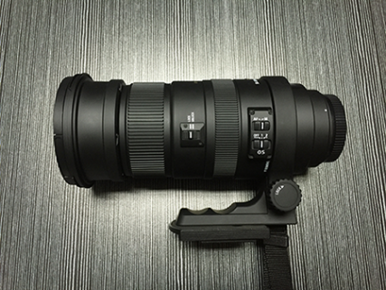
- Camera lens*1 ( sigma50-500 is recommended ).
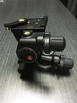
- Tripod head*1 (Manfrotto 410 is recommended)
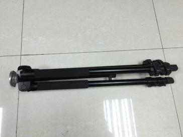
- Tripod*1 (Manfrotto 055DB is recommended)
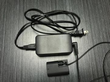
- AC adapter of canon camera*1 (alternative)
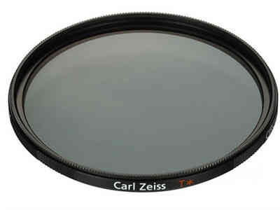
- ND filter (alternative: using it in the condition of outdoor high brightness screen, ND400 is recommended)
1.2 Camera Assembly
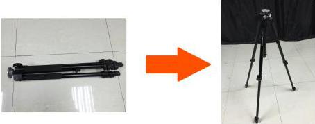
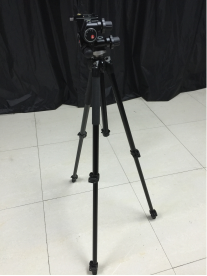
1.2.1 Open the tripod
As shown in figure 1-7.
1.2.2 Tripod Head Installation
Align the mounting hole at the bottom of tripod head with the positioning bolt of the tripod, and turn the head clockwise tightly. As shown in figure 1-8.
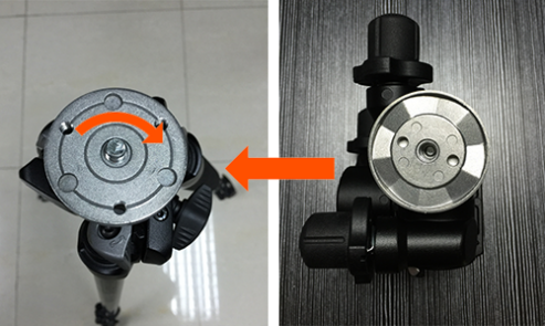
Finished installation as shown in figure 1-9
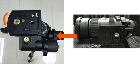
1.2.3 Lens Installation
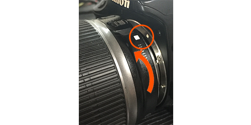
(1) Following fig.1-10 arrow direction, toggle the release lever of the heads to the appointed position..
(2) Adjust the lens direction consistent with the head’s.
(3) Follow the steps below to complete lens installation:
Firstly, insert the base rear of the lens clip into the dovetail groove of the heads. And then press the front of the lens, and the release lever will rebound automatically. Finish lens installation, as fig.1-11 shown.
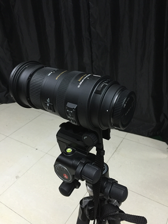
1.2.4 Camera Installation
(1) Rotate and remove the lens cover and the body cover.
(2) Camera Installation: as shown in figure 1-12.
Firstly, to align the red or white mark between the lens and the camera; secondly, pushing the lens into the camera; lastly, to rotate the camera in the direction of the arrow shown until the lens snap into place.
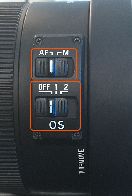
(3) Switch the lens focus mode to <AF>, and turn off the optical stabilizer(OS for Sigma, IS for Canon), as shown in figure 1-13.
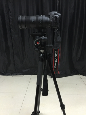
(4) For now, camera installation is complete (as shown in figure 1-14). Connect the camera to the computer via USB cable, and now you can begin to calibrate.
1.3 Software installation and un-installation
1.3.1 Colorlight Calibration Software Installation
- Download Calibration Pro V6.5 from our website and unzip it to your computer desktop.Double-click the colorlight Calibration software icon
 , select a language
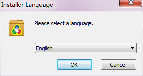
Fig.1-15 Installer language
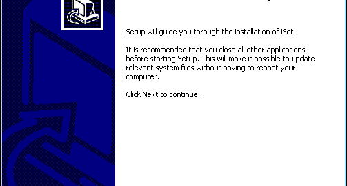
2) Enter welcome interface.

Fig.1-16 Welcome page
3) Choose a directory for installation and click [ Next ].

Fig.1-17 Choose install location
4) Choose components.

Fig.1-18 Choose components
5) Finish colorlight Calibration software installation

Fig.1-19 Setup completion
Colorlight Calibration software can be run directly after installation, desktop shortcut will be generated automatically by system, right-click  and choose [Run as administrator] to run the client application, right-click
  and choose [ Run as administrator ] to run the server application.
1.3.2 Un-installation
Internal uninstall application: select [ all application→ calibration→ uninstall ] from the start menu, colorlight calibration software user manual can be removed automatically.

Fig.1-20 Uninstall application
2. Calibration Instruction
2.1 Colorlight Calibration Software interface
When open the colorlight calibration software, the main interfaces (shown as fig.2-1) will appear. Preview interface is for server application and operation interface is for client application, also work when you separately run them on two computers.
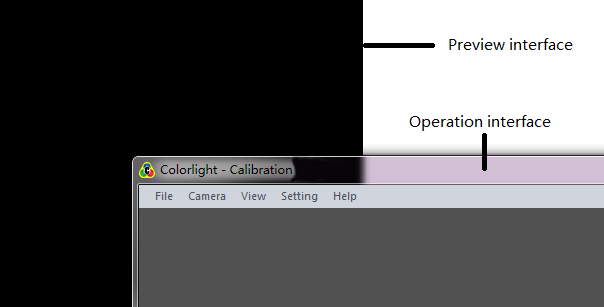
Fig. 2-1 Calibration Main interface
2.2 Menu and shortcut icon
2.2.1 File menu
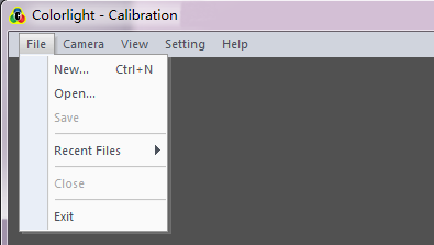
Fig. 2-2 File menu
[ New ], [ Open ], [ Save ], [ Recent Files ], [ Close ]: Basic operation on files in the form of *.cali.
[ Exit ]: Turn off the colorlight calibration software.
2.2.2 Screen control menu
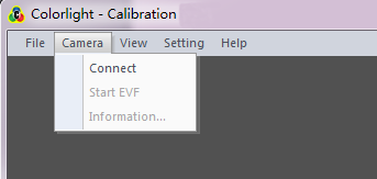
Fig.2-3 Display control menu
[ Connect ]: Connect the colorlight calibration software to the camera; all the camera parameters can be set by colorlight calibration software.
[ Start EVF ]: To make the camera under viewfinder status, check the setting status by observing any real time image appeared on camera screen.
[ Information ] : Acquire relevant information about camera type, etc.
2.2.3 Setting menu
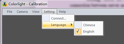
Fig.2-4 Setting menu
[ Connect ]: Check the connection between receiving card and computer or the connection between server and computer.
2.2.4 Help menu
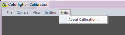
Fig.2-5 Help menu
[ About calibration ]: Check the version of the colorlight calibration software.
3. Integrated calibration
3.1 Configure the screen
Set the right parameters for display through LEDVISION ( disable brightness calibration), then send and save the setting data to the receiver card.
Note: please close the LEDVISION after configuring parameters, then enter to Calibration.
3.2 Connect to Server
Running calibration, select [ setting -> Connect ] to enter setting page, and input the correct server IP. (Running CMD.exe and input [ ipconfig ] then you can get this computer IP address is 127.x.x.x). The server port is the same as the client (the server port default is 9933, please do not change if not necessary)
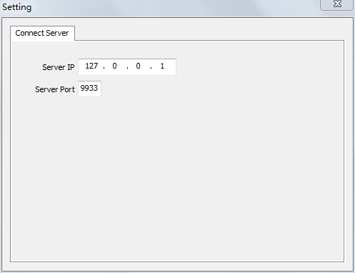
Fig. 3-1 Server Port Connect Window
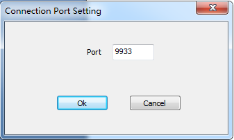
Fig. 3-2 Server Connection Pot Window
Check the colorlight calibration software client status bar to make sure the client and server port has been connected. As shown in Fig.3-3.
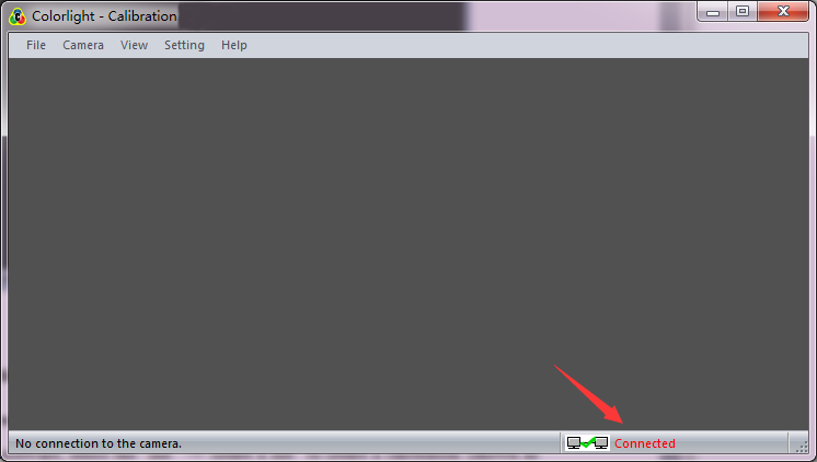
Fig.3-3 Successful Connection Tip
3.3 Create a New Calibration
Step 1: New Project Wizard-1
Open the software, select the [ file → New file ] to create a calibration (shown as fig. 3-4)
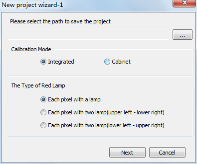
Fig.3-4 Project Creation Window
Choose for storage location, calibration mode, and the type of red lamp:
[ Storage location ]: Used to store the images and coefficient files generated during calibration process;
[ Calibration Mode ]: Integrated calibration and single cabinet calibration are available
[ The Type of Red Lamp ]: Select a right red lamp type;
Step 2: New Project Wizard-2
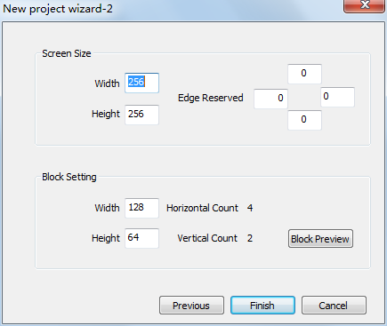
Fig.3-5 Project Window Properties
Screen options on calibration (shown as fig.3-5) includes: [ Screen size ], [ edge reserved ] (zero as default), and [ block setting ] (first to deal as default, settings can be changed in [ basic parameters ] setting).
3.4 Connection between net card and display
Click [ Setting…] button in [ basic parameter ] page to open the [ Net Card Setting ] dialog (as shown Fig. 3-6). Then Click [ Detect ], to make sure if all the receiver cards can be detected accurately.
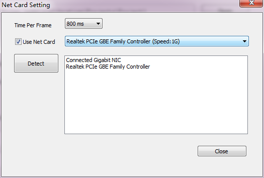
Fig. 3-6 Internet Access Window
3.5 Basic parameter setting
Fig. 3-7 Basic Parameter Setting Window
Corresponding to select the send mode and the receiver card series, if you are not sure the receiver card series, please click the [ Auto-Detect ] for automatic detection;
Set the actual size and offset of the screen to the correspond editors, and the edge reserved should according to the field situation;
Block setting: The numerical size is determined by camera resolution. For Canon 7D MarkII, we suggest width* height is 150*100 if not check the [ Enable Skip Points ].
Note: The last row and the last column cannot be too small; setting can be checked in [ modify block size ] (as shown fig. 3-8).
Please enable skip points and set the point number in [ modify block size ] if you need.
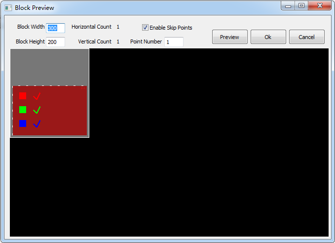
Fig.3-8 Block Preview Window
Select [ block preview ] → [ block map ], and choose one block from it as camera adjustment area. At this time, the corresponding area on LED screen will be selected and lighted (present in the form of white frame plus LED tricolor).
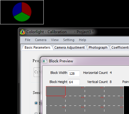
Fig.3-9 Operation Effect
3.6 Camera preparation
1. To set up the camera
2. Start the camera and shift to M mode, and then connect to the computer via USB cable.
3. Select the menu [ camera ] → [ connect camera ].
4. Select [ camera ]→ [ start EVF ], at this time, the real-time scene can be seen on the monitoring area.
5. Accommodate camera to enable the selected area of the LED display to fall into the white square frame of monitoring area.
a) The selected area should be parallel to the square frame.
b) The selected area should be filled in the white square frame. A little overpass is permitted but not too much.
c) The selected area cannot be larger than the monitoring area.
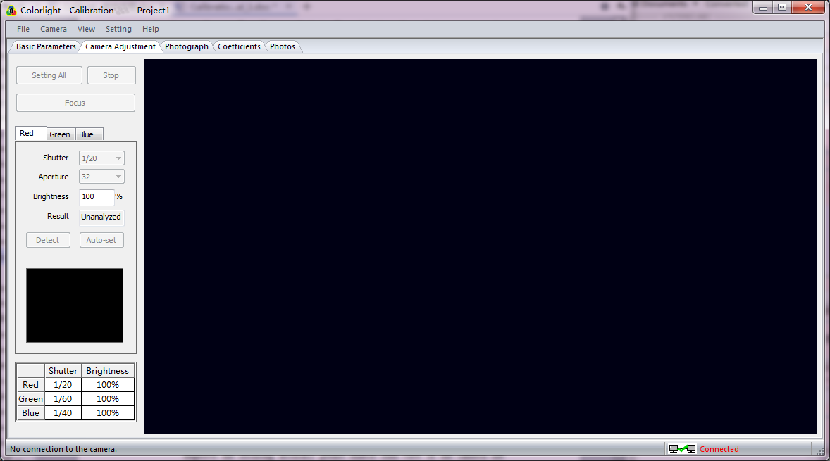
Fig. 3-10 EVF
6. Shift the focus mode to AF, select [ Camera Adjustment ] →[ focus ] ( In order to improve the focusing accuracy please enable find view or the camera use [ live ] mode before focus.
7. Release the button in 3-5s, shift the focus mode to MF and lock after finishing focus. Monitor area shown as fig. 3-11.
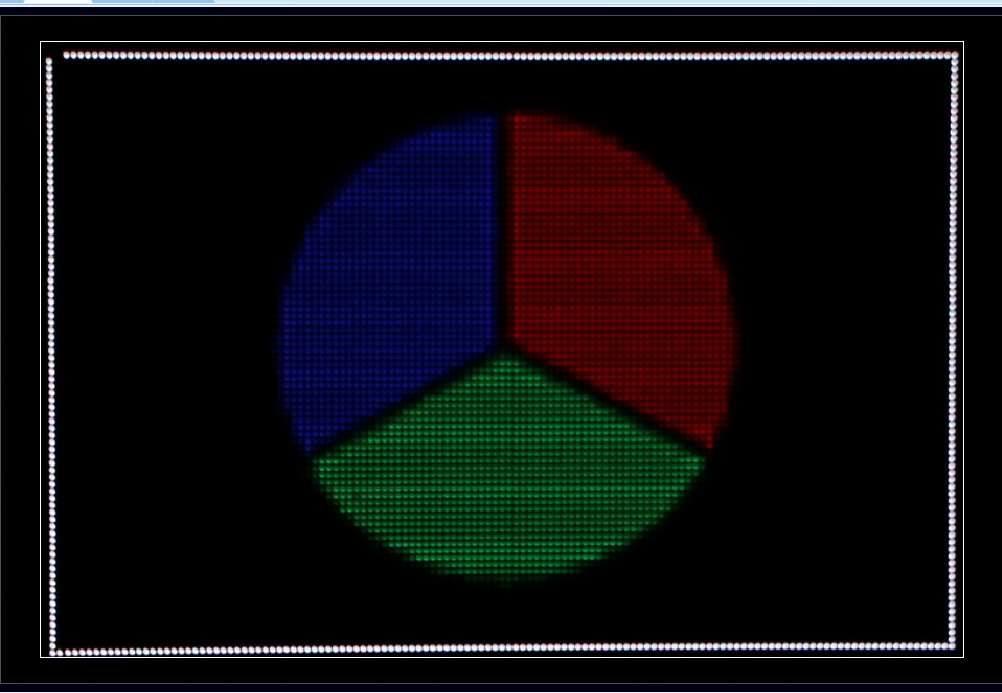
Fig. 3-11 EVF (Clear Focus)
3.7 Camera adjustment
Automatic setting:
Click [ Setting All ] to detect red, green, blue automatically.
Manual Setting:
- Click the [ detect ] button under red, green, blue, histogram generated from the image automatically taken by camera will be shown within the black square frame.
- Check the histogram in preview frame to see shooting effect.
a) The standard histogram: the lower right corner of the corresponding color slope should be closed to the lower right corner of the square frame, staining to the right edge is not permitted.
b) Example in red:
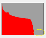
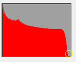
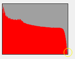
i ii iii
Fig. i too faint, fig. iii too bright, fig. ii standard
- Adjust relevant parameters according to the above standards. Re-auto setting or manual setting can be made if the picture can not meet requirements. Rules of manual settings listed as below:
1.When too much bright
- Reduce the shutter time (requires refresh rate increased)
- Lower brightness percentage
2.When too faint
- Increase the shutter time (requires environment improved)
- Increase brightness percentage
- Repeat step1-step3, to confirm picture histogram meet the requirements.
Note: Parameters change together with camera adjustment. Please save new setting parameters after the accomplishment of shutter adjustment.
3.8 Shooting photos part
1. Select one block from the [ Shooting photos ] in the partition map, then click [ Monitor ].
2. Adjust the camera to make the screen displayed area position in the preview area of the white box of Tab [ shooting photos ] .
3. Click [ Batch Shoot ] in photograph page, the RGB matrix of the region was taken by each one (a few photos if skip points is enabled).
4. After shooting photo, the corresponding block area will display RGB matrix in the partition map. In the case of shooting failed, click [ Reshoot ] to reshoot the failed photo if enable the skip points function.
5. After shooting a selected block of RGB, the screen will automatically display the next block. Repeat step 2-4, to complete shooting photos for whole screen.
Note: If you set up [ Deseam Only ] in the [ basic parameters ] setting page, only need to shoot red color in each partition.

3.9 Generate coefficient
3.9.1 Brightness extraction
Start brightness extraction for images with clicking [ start analysis ] on [ shooting ] after shooting. (when completed the analysis of corresponding RGB images, a check mark will appear in corresponding area, as fig. 3-13 shown).

Fig. 3-13 Start Analysis
Analysis going with shooting can save lots of time if the computer has a good configuration.
3.9.2 Generate coefficient
1. The extracted brightness maps can be checked by selecting [ Coefficient ] →[ Brightness Chart ], as fig.3-14 shown.

Fig. 3-14 Brightness Chart
2. [ Brightness(%) ]: Percentage of RGB means the retained brightness percentage after calibration (default value is 85)。
3. A calibration coefficient will be created and saved in memory until the analysis of all images have been done (part of images that have been completely analyzed can be checked).
4. After generating integrated coefficient, send the calibration coefficient to server by clicking [ Send to Server ] button.
5. Select [ Calibration by PC ], then select [ start calibration ], calibration effect can be checked by clicking [ White ], [ Red ], [ Green ] or [ Blue ]. Effect before and after calibration can be checked by switching [ Calibration by PC ] and [ Disable Calibration ].
6. After generating integrated coefficient, send the calibration coefficient to the receiver card by clicking [ Save to Receiver ]. As the sending time is too long, please be patient and wait for the completion.
7. After saving the coefficient to receiver, click [ Calibration by Receiver Card ] to enable calibration. (please make sure all the receiver cards have been detected before saving)
8. [ Export ] the coefficient and save as .3fcoef file to computer for following maintenance.
4. Single cabinet calibration
4.1 Create single cabinet calibration
Create a new calibration, select [ Calibration Mode ]→ [ Single cabinet calibration ], set cabinet dimensions on New project wizard 2, and create multiple cabinets in the same batch.

Fig. 4-1 single cabinet calibration

Fig. 4-2 single cabinet calibration
4.2 Shooting process
4.2.1 Camera adjustment
Camer adjustment refers to section 3.6, 3.7.
4.2.2 Shooting

Fig. 4-1 single cabinet shooting
- Click the [ Start Analysis ] button, which means that it will analyze the photo while taking photo at the same time, to save the calibration time. Users with poor computer configuration, we recommend that click the [ Start Analysis ] after taking photo, waiting until analyzing is completed, then stop analysis and start shooting next cabinet.
- Click the [ Batch Shoot ] button, and start shooting from the first cabinet.
- After analysis completed ( Fig4.2 ,when three colors present √, it means that all the analyses are completed), the correct coefficient will be auto sent to receiver card (By default, the coefficient will be sent to receiver card automatically. Or, you may uncheck [ Auto Save Calibration Coef ] to disabled the function.).
- After saving the calibration coefficient, it will pop up a dialog box. Calibration mode will be turned on automatically in i series mode, if in classic mode, you need to turn it on manually. Click [ OK ] on the dialog box, it will switch to next cabinet automatically, by switching to different colors,you can check calibration effect.
- Mark the cabinet and then change to the next cabinet, repeat step 2 to 4 until all the cabinets are calibrated.

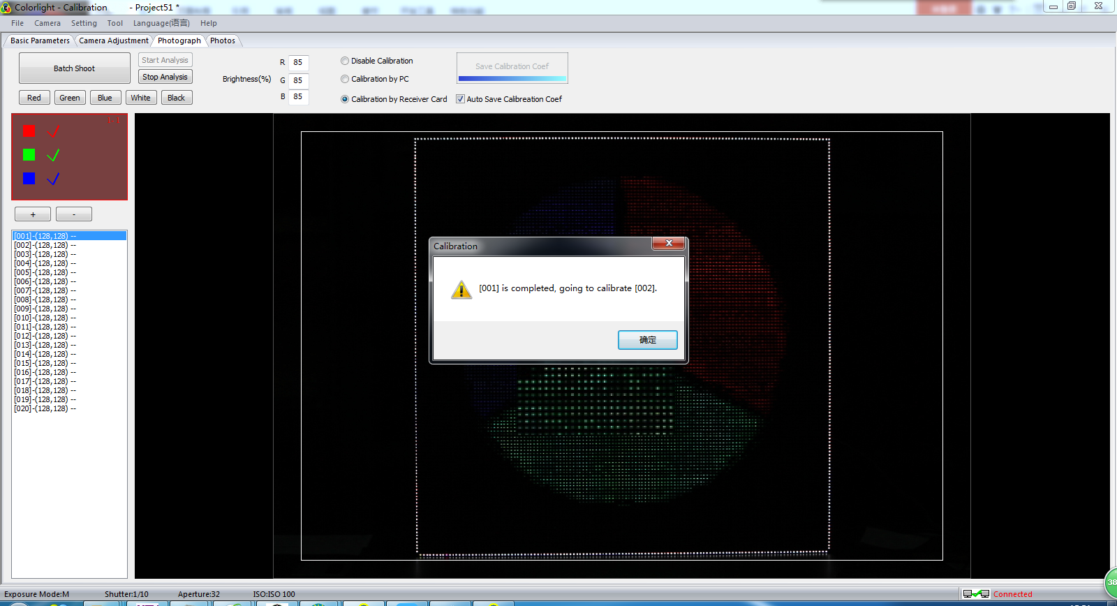
Fig. 4-2 single cabinet analysis5. Brightness and Chroma calibration
1. Select [ Brightness and Chroma ] as calibration type in [ coefficient ] page. As shown in Fig.5-1.

Fig.5-1 Select “Brightness and Chroma” Calibration
2. Color gamut setting

Fig.5-2 color gamut setting
- According to the data collected by equipment, input the brightness and chroma data manually before calibration.
- After inputting the trichromatic data, collect the white data to verify.
- Color gamut:
We recommend using [ Calculate Color Gamut Automatically ], it can calibrate the different chroma under the retain gamut in maximum and reduce chroma loss.
Please input the coordinate of target color manually if the users have special requirements for color gamut.
Built in sRGB color coordinate parameters.
d) White balance:
We recommend using [ Keep White Point Not Moving ], the built-in algorithm will keep the white point coordinates before calibration.
Please input the coordinate of target white point manually if the users have special requirements for white balance.
Built in D65 color coordinate parameters.
e) Color temperature:
If you need to change the color temperature, you can uncheck [ Keep White Point Not Moving ], then input the target color temperature, built-in algorithms will automatically calculate the color coordinates.
6. Suggestion on calibration
- Shift the camera to M mode.
- Gray scale and brightness can not be modified at random while shooting. Because changes will have impacts on RGB color photos;
- Calibration is suggested to take at night, a better brightness uniformity is the key point.
- Calibration can make a better uniformity but a reduction on brightness
- After calibration, view from front is the best, viewing angle and viewing effect from side can not be improved.
7. FAQ
1. Ensure the stable connection between hardwares.
2. Improve the frame time.
3. Select the right net card under the drop down list.
1. Ensure the stable connection between hardwares.(If the hardware connection is normal, the NIC should light on.)
2. Make sure the target IP is correct (the local IP is 127.X.X.X) by executing ping command.
3. Make sure the server port is the same as the client.
Try to telnet the target port (Generally, if you can ping the target IP but cannot connect to the target port, it was mainly disable by the firewall or router).
A: Please adjust the screen to normal status via LEDVISION and then save it to the receiver card.
1. Confirm that the camera model is supported by the software (Software currently only support part of the Canon camera, please contact the technical support for details), please pay attention that the EOS 7D is not the same as the EOS 7D MarkII.
2. Confirm the stable connection between hardwares.
3. Confirm that the camera is open but not dormant.
4. Confirm that the camera is shift to manual mode (M mode).
1. Confirm that the camera model is supported by the software (Software currently only support part of the Canon camera, please contact the technical support for details), please pay attention that the EOS 7D is not the same as the EOS 7D MarkII.
2. Confirm that the camera is shift to manual mode (M mode).
3. Close the lens auto-focus function.
1. Confirm that the camera is shift to manual mode (M mode).
2. Confirm that the multi-function dial is set to shooting mode instead of movie mode.
1. Confirm that the camera model is supported by the software (Software currently only support part of the Canon camera, please contact the technical support for details), please pay attention that the EOS 7D is not the same as the EOS 7D MarkII.
2. Try to re-install the software to ensure that components are completed.
3. Please check the shooting quality. Check it like this: click [ open…] in the [ Photos ] page, then using brightness extract, grey-scale map or histogram function to manual analysis photos whether there is out of focus, overexposure, underexposure, shake, etc.
4. Partition is so large that leads to the dense lamp. (Using the skip point function to reduce lamps density)
5. Too much broken point/dislocation can affect the results of the analysis.
6. The available memory is limited.
Out of focus:
1. SLR cameras need to start EVF or use the camera’s LIVE mode focus in order to improve the focusing accuracy.
2. Using manual focus to improve accuracy when the auto focus effect is not good enough.
Overexposure/underexposure:
Reset the correct camera parameters on the camera adjustment page.
Share:
1. Make sure the shooting system stability.
2. Close the lens and the camera stabilization function.
A: Brightness calibration makes the screen even by reducing the lighter point brightness, thus the screen brightness will decline after calibration.
Chroma calibration makes the screen even by reducing the saturation, and it contains the function of the brightness calibration, thus the screen brightness and the saturation will decline after calibration.
1. Please check the shooting quality. Check it like this: click [ open… ] on the [ Photos ] page, then use brightness extract, grey-scale map, or histogram function to manual analysis photos whether there is out of focus, overexposure, underexposure, shake, etc.
2. Partition is so large that leads to the dense lamps and increases the sampling error.
3. If the gamma table referred to by the simulator is not the same as the target, please send parameters to receiver cards.
1.Shutter speed is too fast, you need to set the shutter slower, and reduce the screen brightness darker to maintain the brightness at the same time.
2.The refresh rate is too low, you need to increase the refresh rate.
The phenomenon is caused by the interference system error of the lamp frequency and the pixel frequency.
The system error is divided into two parts, the position error and the brightness error.
Solutions:
1. Confirm the frame was filled with images.
2. Decreasing partition and increasing focus (You need to re-photometry after adjusting the focus).
3. Decreasing focus slightly (You need to re-photometry after adjusting the focus), and then you will shoot in a slightly out-of-focus condition (But this measure requires the focusing error can not be too large). Enable the skip point function to improve the spacing if you need.
4. Close deseam function for the impact of the position error can be eliminated.