colorlight iSet software user operation manual
Colorlight iSet software content
Table of contents
Chapter 1 colorlight iSet software Introduction
1.1 iSet Overview
Colorlight iSet software is a software that Colorlight designed and developed for users. It is both professional and user-friendly, with the following characteristics:
- Easily and rapidly set up mapping of complex and large LED screens and LED billboards.
- Quickly adjust screen parameters such as the screens’ brightness and colors
- Convenient to detect and diagnose the screens
1.2 iSet Operating Environment
iSet supports operating systems of Windows XP\Windows7\Windows8\Windows10.
The suggested computer configuration is:
Chapter 2 Installation and Uninstall
Double-click the installation program of iSet, choose the Installer Language:
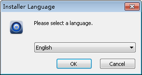
Image 2-1 Choose Language
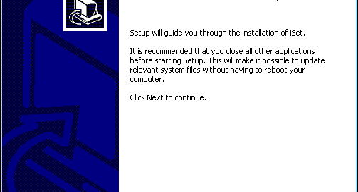
Choose “Next”:

Image 2-2 iSet Setup
Choose the Destination Folder, and then choose “Next”.

Image 2-3 Destination Folders
Install components, choose all on the first time of installation, click “Install”. When reinstalling iSet, only default as checking basic components, other installation components are default as not install:

Image 2-4 Installation components
When component installation is completed, click “Finish” to finish installation.

Image 2-5 Installation Completed
Open Installation Directory of iSet, choose to double-click the ![]() program, the software will pop up a dialog box asking “Are you sure uninstall the iSet?”, click “Yes” to uninstall iSet.
program, the software will pop up a dialog box asking “Are you sure uninstall the iSet?”, click “Yes” to uninstall iSet.

Image 2-6 Software Uninstall
Chapter 3 iSet Quick Introduction

Image 3-1 iSet Main Interface
Open iSet after iSet has been installed; we can see that iSet has four pages, Device Information, Design, Control and Soft Edge.
- Device Information Page: mainly used for detecting device information, such as detecting Sender information, and detecting Receiver Card information.
- Design Page: mainly used for designing the layout of the screen, such as designing Sender layout, designing cabinet layout.
- Control Page: mainly used for setting the screen parameters of Senders.
- Soft Edge Page:Recovering the gaps between cabinets and modules of high resolution caused by processing and installation errors through adjusting calibration parameters.
Mainly used for detecting device information, such as detecting Sender information, and detecting Receiver Card information.

Image 3-2 Device Information Page
- Sender Information
Click on the “Detect Senders” button, the viewing area for Senders will show the Senders’ serial numbers, names, types, video signal information, the amount of Receiver Cards that has been connected to each net port, and the information of the Senders’ firmware version.

Image 3-3 Sender Information
- Receiver Card Information
Click “Detect Receiver Cards”, the viewing area for Receiver Cards will show which net ports on the Senders that the Receiver Cards have been connected to, the Receiver Cards’ serial numbers, types, temperature, network cable status, and working time. Click “all port”from the “Port Filter”or choose single port of “1/2/3/4” to select the receiver info to be displayed from the port needed.

Image 3-4 Receiver Card Information
- Only display unqualified network cable
Click “only display unqualified”, the receiver card display area will display the receiver cards that have unqualified network cables in sequence. When not click on “Only display unqualified”, the receiver card display area will display all the receiver cards.
- Detect Network Cable Status
- Network Cable failed
If the connection of network cables is not stable and the error ratio is larger than 1/1000000000, detect Receiver Card, the viewing area will show “Network Cables Failed”.
- Network Cable Repair
When network cables failed, the network cables need to be repaired, such as taking out and reconnecting the cables, replacing the cables with higher quality ones, and so on.
- Reset Status of Network Cables
After the cables are repaired, we need to clear Receiver Cards’ error packet count to zero, and set the Receiver Card to recount. Move the mouse to the position of the cable, right click on it, and reset the status of the network cables from the Context Menu.
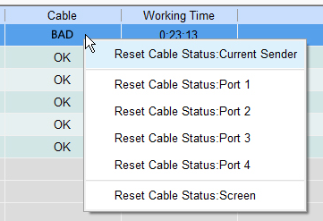
Image 3-5 Reset Status of Network Cables
The Design Page is mainly used for designing the layout of the screen, such as designing Sender layout, designing cabinet layout.
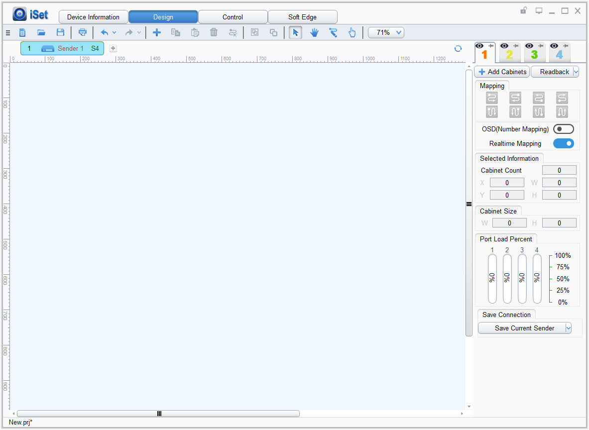
Image 3-6 Design Page
- Add Cabinets
There are three steps to directly add cabinets in iSet: choose net ports, choose cabinet types, and add cabinets.
- Choose Net Ports
The senders have several net ports, first we choose Sender net ports that need cabinets to be added.
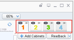
Image 3-7 Choose Net Port
- Choose Cabinet Types
Choosing cabinet type falls into two categories: choosing cabinet types that are known and choosing cabinet types that are unknown.
If the corresponding product type already exists in Type Management, directly choose to add cabinets of that product type.
If the corresponding product type does not exist in Type Management, custom adding cabinets according to the actual size of the cabinets.
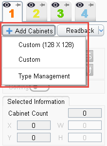
Image 3-8 Choose Cabinet Types
- Add Cabinets
After choosing product type, hold the left mouse button on the View Area and move the mouse, to add certain amount of cabinets.
Besides adding cabinets directly, we can also add cabinets through Readback. If the mapping of the cabinets is already working well, we can click the “Readback” button to readback the cabinets.
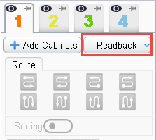
Image 3-9 Readback
- Set the Array of Cabinet Groups
After adding certain amount of cabinets, if the array of the cabinets does not match with real situations, then the array needs to be set: left click to choose cabinet groups and hold the Ctrl key, at this time, the lower right corner of the cabinet group will have a small box showing up, drag the small box using the mouse to set the array of the cabinets to match with real situations.
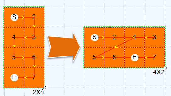
Image 3-10 Set the Array of the Cabinets
- Set Up Mapping
Cable connections will be automatically created when adding cabinets on iSet, but if the connections do not match with real situations, we need to reset the connections either through Auto Routing or Manual Routing.
- Auto Routing
Choose the cabinets that need routing, use the 8 patterns that iSet has pre-set to quickly set it up.
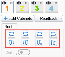
Image 3-11 Auto Routing
- Manual Routing
Click on the “Manual Routing” button  , put the mouse on the cabinet and left-click on it, route the cabinets one by one.

Image 3-12 Manual Routing
- Clearing Routing
To cancel the routing of the routed cabinets, right-click on the routed cabinets, iSet will cancel the mapping between this cabinet and the following cabinets.

Image 3-13 Cancel Routing
We can also click on the “Clear Mapping” button ![]() on the toolbar, to clear all the mapping at the current net port.
on the toolbar, to clear all the mapping at the current net port.
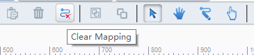
Image 3-14 Clear Mapping
Setting mapping has two auxiliary functions: Realtime Mapping and Sorting.
- Realtime Mapping
First turn Realtime Mapping on; when the mapping has been changed in iSet, we can see the results on the screen in real time.
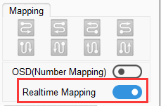
Image 3-15 Turn Realtime Mapping On
- OSD(Number Mapping)
Open OSD, at this time the cabinets will show the numbers according to the actual cable connections of the screen.
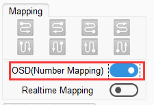
Image 3-16 Open OSD
- Save the Mapping of the Cabinets
When the mapping of the cabinets has been set, click “Save Current Port” to save the mapping of the cabinets.
We can save the mapping of the screen controlled by one Sender to Receiver Card, Or save the mapping of the whole screen loaded by multiple senders all at once.
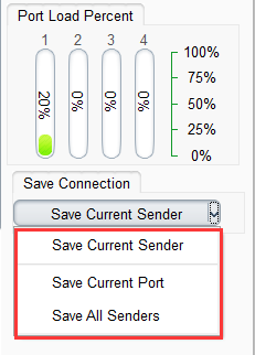
Image 3-17 Save Mapping of Cabinets
- Save and Open Projects
After setting the mapping of the screen, besides saving to cabinets, we can also save as a project file. Click on the “Save Project” button, save the mapping of the screen as a project file. Similarly, we can click on the “Open Project” button, to directly load the saved project files into iSet.
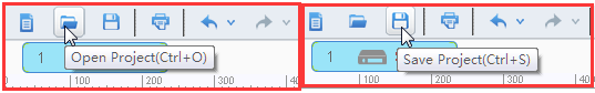
Image 3-18 Save, Open Project
After setting the mapping of the screen, we can print it out as installation drawings for staffs on set.
Click on the “Print” button ![]() on the toolbar of iSet, enter the Print Preview Window, at this interface we can print out the mapping of the cabinets connected with Senders.
on the toolbar of iSet, enter the Print Preview Window, at this interface we can print out the mapping of the cabinets connected with Senders.
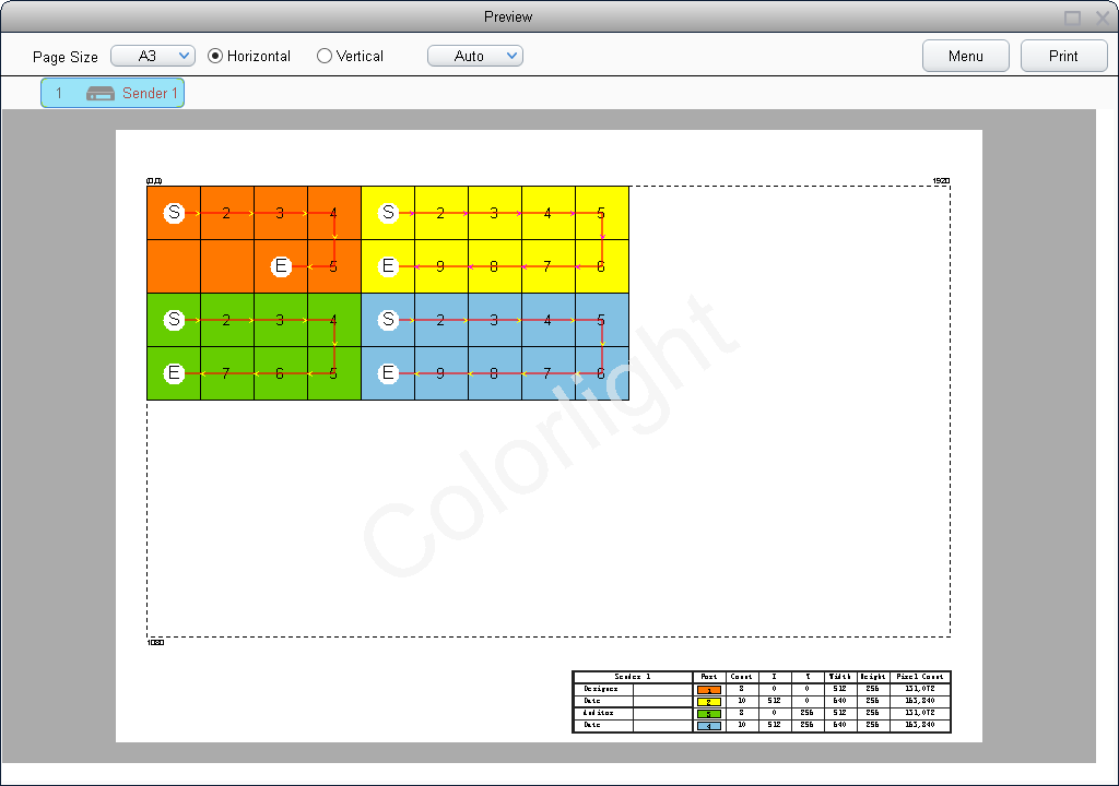
Image 3-19 Print Preview Window
The Control Page is used for setting screen parameters of Senders, which mainly are brightness, colors, test patterns, Freeze screen, and black screen.
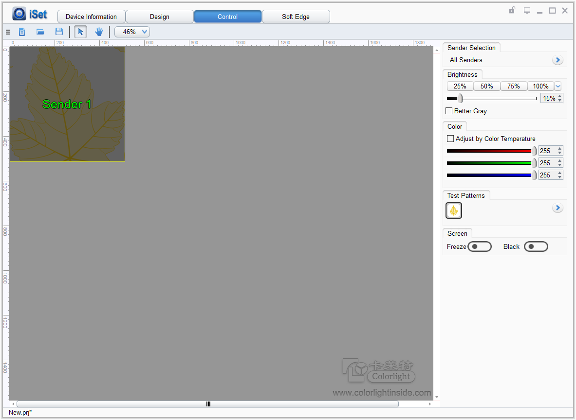
Image 3-20 Control Page
- Brightness Adjustment
Under “Brightness”, we can quickly set the brightness of the Senders by using the four pre-set buttons, or by using the slider.
We can set the Senders’ brightness value. We can also set Better Gray of the Sender. We can Turn Better Gray on to optimize the displaying results of the screen under low brightness.
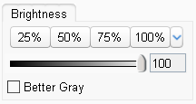
Image 3-21 Brightness Adjustment
- Screen Color Adjustment
We can adjust the colors of the LED screen by setting color temperature. Use the mouse to slide the slider to set up color temperature. The adjustable range of color temperature in iSet is 2000-10000. Click on “Default”, we can quickly set up the color temperature to 6500.
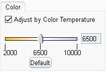
Image 3-22 Adjust by Setting Color Temperature
If unchecking the “Advanced Settings” option in iSet, we can also adjust the colors of the LED screen by setting the brightness of Red, Green, and Blue.
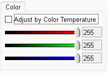
Image 3-23 Adjust by setting Red, Green, and Blue
- Test Patterns
Click on a certain Test Pattern Icon, the Senders will show the corresponding effects. Through Test Patterns, we can view the display of the screen, detect and diagnose the screen.
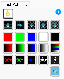
Image 3-24 Test Patterns
- Freeze and Black
We can also set “Freeze” and “Black”.
Click on “Freeze”, the picture on the screen will freeze; Click on “Black”, the screen will become black and display nothing.
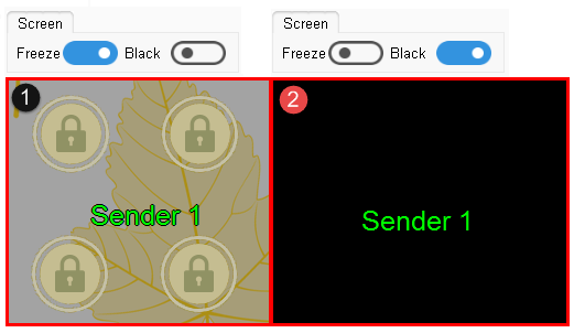
Image 3-25 Freeze and Black
Chapter 4 Detailed Introduction of iSet
The home page of iSet is mainly formed by 4 pages: device information, design, control, and Soft Edge. After turning “Advanced Authorization”on, the display of Soft Edge page can be closed.

Image 4-1 iSet Main Interface
Click the iSet Icon ![]() , to pop up the main menu, the main menu includes 5 pars: Language, Set, Advanced Authorization, Help, Release Notes, and About.
, to pop up the main menu, the main menu includes 5 pars: Language, Set, Advanced Authorization, Help, Release Notes, and About.
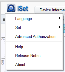
Image 4-2 iSet Setting Page
- Language
First time opening iSet after installation, iSet will choose the language based on the current system environment. iSet supports Chinese-English switch, after switching the language, iSet will save the settings.
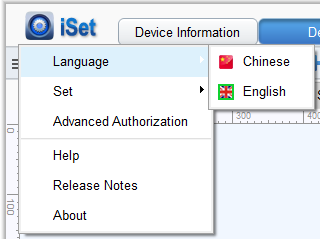
Image 4-3 Choose Language
Click on “Language” to switch to English, the software interface will show as the picture below:

Image 4-4 iSet English Interface
- Settings
We can set Show Grid, Enable Attraction and shortcut key settings .
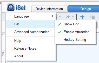
Image 4-5 Basic Settings
- Show Grid
After “Show Grid” has been checked, in the View Area under the Design Page, the View Area is divided based on the size of the cabinets. If unchecking “Show Grid”, the View Area under the Design Page will not be divided.

Image 4-6 Show Grids
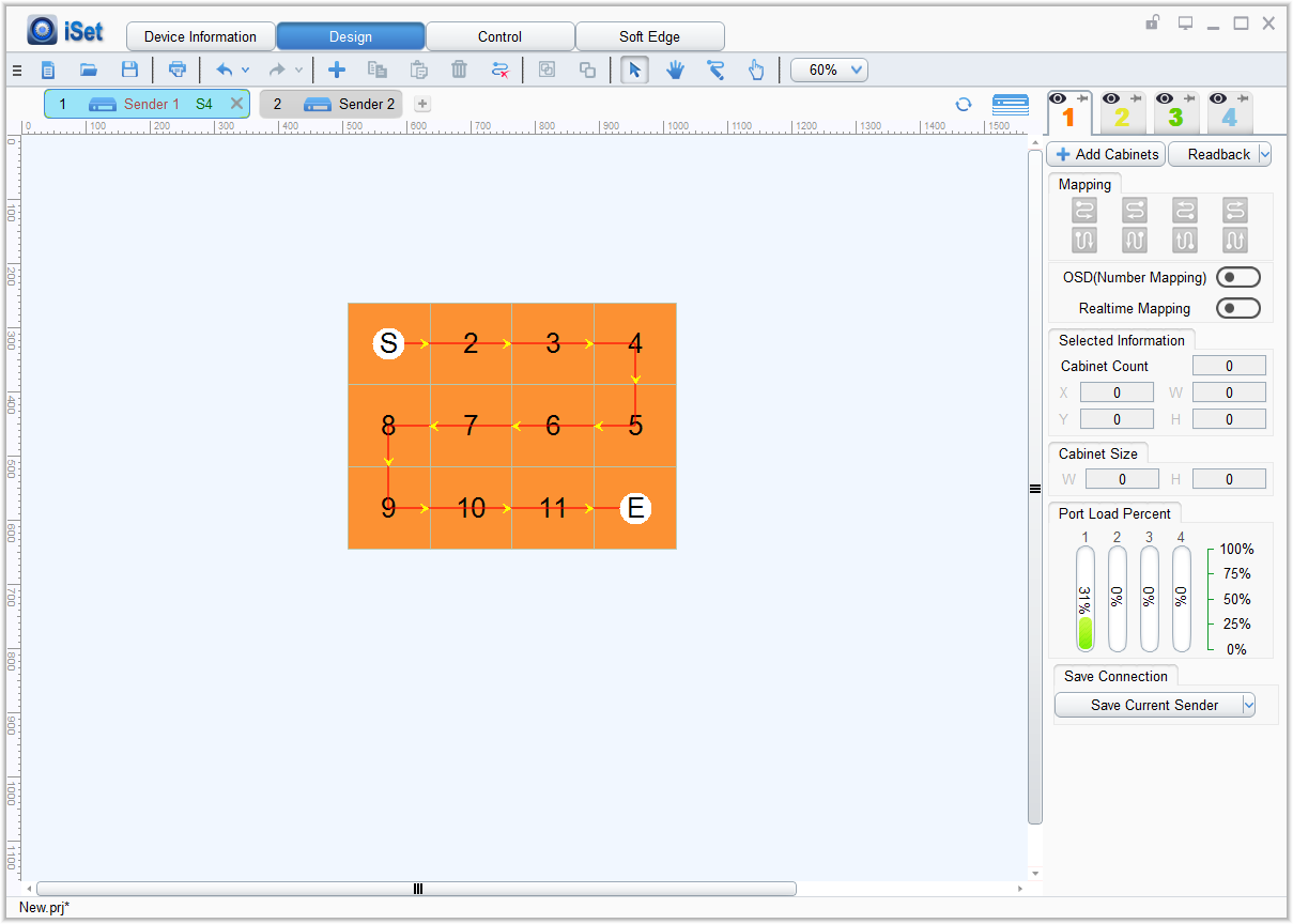
Image 4-7 Do Not Show Grid
- Enable Attraction
When “Enable Attraction” is checked in iSet, when the selected cabinet group is close to other cabinet groups, the cabinets will automatically be attracted to the nearby cabinet group. When the cabinet group is close to ruler line, the cabinet group will automatically be attracted to the ruler line. If unchecking the “Enable Attraction” function, then there will be no such effect.
- Shortcut Key Settings
Choose Shortcut key settings, users can set up shortcut keys, which makes operations of software more convenient.
- Advanced Authorization
iSet will open the on/off for customizations of advanced functions after turning on Advanced Authorization, advanced functions includes: display soft edge, turning on readback basic parameters, turning on saving basic parameters.
The authorization will be successful after inputting in the correct password.
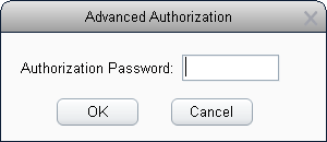
Image 4-8 Advanced Authorization
- Help
Click on help, a Chinese help document will display on the Chinese version of help interface, an English help document will display on the English version of help interface.
Image 4-9 English Help Document
- Release Notes
Click on “Release Notes” option, iSet will display the updated logs of the current version.
- About
Click on “About”, information such as the software version, Build Number (Build Time), and company name, will display.
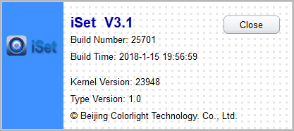
Image 4-10 About
The Device Information Page is mainly for detecting Sender information and Receiver Card information. On the left of the interface a “Detect Senders” and a “Detect Receiver Cards” button will show up. List of corresponding Sender information and Receiver Card information will show on the right side.
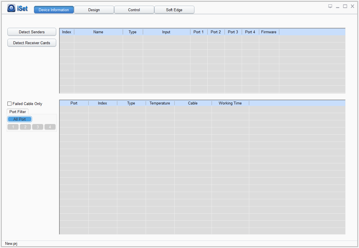
Image 4-11 Device Information Page
Used for detecting Sender information, click the “Detect Senders” button, the software will show the detected Sender information on the Sender information list.
Contents displayed on the Sender information list are: Index, Name, Type, Input, Ports, and Firmware.
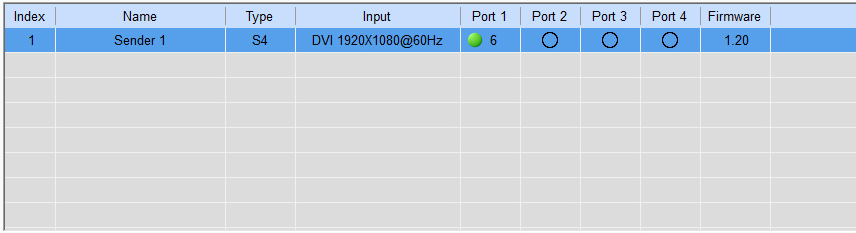
Image 4-12 Sender Information List
- Index: Display the Index of Senders. Through index we can find out the arrangement and amount of Senders.
- Name: The name of the Sender displayed under the Design page is renamed, if it is not named it will show as Sender.
- Type: Display the type of the Sender.
- Input: If the Sender has been connected to video signal, under the “Input” option, the type of input and size of video signal will show. If the Sender has not been connected to video signal, on the row of“Input”, there is no signal.
- Ports: Display the status of net ports connecting with Receiver Card. The green circle stands for Receiver Cards have been connected to this net port, the number next to it is the amount of Receiver Cards; the hollow circle stands for no Receiver Card has been connected; if the net port does not exist, use “–”to represent.
- Firmware: Display the firmware version information of the Sender (FPGA firmware and ARM firmware). The FPGA firmware of the Sender will directly be displayed. To show the ARM firmware of the Sender, we need to move the mouse to the position of FPGA firmware.
Used for detecting receiver card information, click “detect receiver card”button, iSet will display the detected receiver card information on the receiver card information list.Click “all netports”from the “select netports”or choose “1/2/3/4” single net port to select the receiver info from the net port needed.
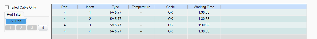
Image 4-13 Receiver Card Information List
- Ports: Display net ports of Receiver Card. The Number of net ports that have been connected to Receiver Card will be displayed in the order of small to large.
- Index: The index of the Receiver Card on net port. The index of the first Receiver Card connected to net port is 1.
- Type: the type of Receiver Card, including Receiver Card type and firmware.
- Temperature: Used for displaying the cabinet temperature detected by Receiver Card. If the Receiver Cards do not have the temperature monitoring function, then on the temperature option, it will show as “–”.
- Cable: Used for displaying the status of the network cable. When the network cables are working well, it will display as “Normal”; when the network cable error rate is high, it will display as “Failed”.
- Working time: the continued working time after the power of Receiver Card is on. If the power of the Receiver Card is off, the time of Receiver Card will be recalculated next time the power is on.
If network cables failed, we can solve it using the following methods:
- Network Cable failed: If the connection of network cables is not stable and error packets higher than 1/1000000000, detect Receiver Card, the viewing area will show “Network Cables Failed”.
- Network Cable Repair: When network cables failed, the network cables need to be repaired, such as taking out and reconnecting the cables, replacing the cables with higher quality ones, and so on.
- Reset Status of Network Cables: After the cables are repaired, we need to clear Receiver Cards’ error packet count to zero, and set the Receiver Card to recount. Move the mouse to the position of the cable, right click on it, and reset the status of the network cables from the Context Menu. For resetting network cable status, we can choose to reset the network cable status of all the net ports of the current Sender, or choose to reset network cable status of a certain net port of the current Sender, or choose to reset network cable status of the whole screen.
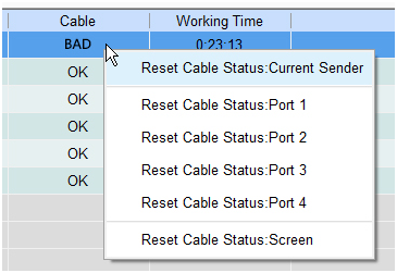
Image 4-14 Reset Network Cable Status
The Design page is formed by four parts: ①.Toolbar, ②Senser Information Column, ③Design View Area, ④Parameter Setting Area. The Design page is the major position for designing the mapping of cabinets, and is also the main position for setting parameters of the cabinets.
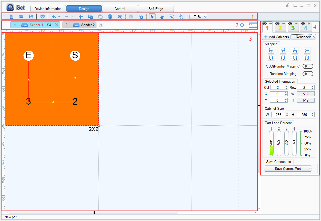
Image 4-15 Design Page
4.4.1 Instructions about Toolbar
The toolbar is an important tool for designing the mapping of the cabinets, through the tools on toolbar; we can easily design the cabinets, and easily process project files. The main content of Toolbar is as the following table:

Image 4-16 Content of Toolbar
- New Project
Click on the” New Project” button or use the shortcut key (Ctrl+N), iSet will create a new project, and the project name is New.prj. If the current project is not saved, before creating the project, iSet will remind the users if the current project should be saved. The content of the project includes data information such as the amount of Senders, the amount and position of cabinets, mapping, and basic parameters.
- Open Project
Click on the “Open Project “button or use the shortcut key (Ctrl+O), to open a project file in the PC, and import the data of the project file into iSet. If the current project is not saved, before importing the project file, iSet will remind the users whether to save the current project.
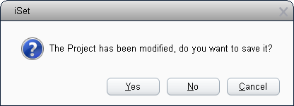
Image 4-17 Save the current Project Reminder
- Save Project
Click on the “Save Project” button or shortcut key Ctrl+S), to export the data of the current project and save as a project file, the project file is saved using the suffix “.prj”, the file name is default as “New.prj”.
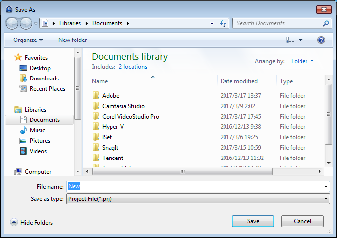
Image 4-18 Save Project Dialog Box
The Print function is supported on the Design page. After the mapping of the cabinets has been set, we can print out the mapping of the cabinets of each Sender, we can also print out the whole layout of the Sender. Click on the “Print” button or the shortcut key “Ctrl+P”to enter the Print Preview Window. The print parameters can be set, and the printing results can be previewed on the Print Preview Window.
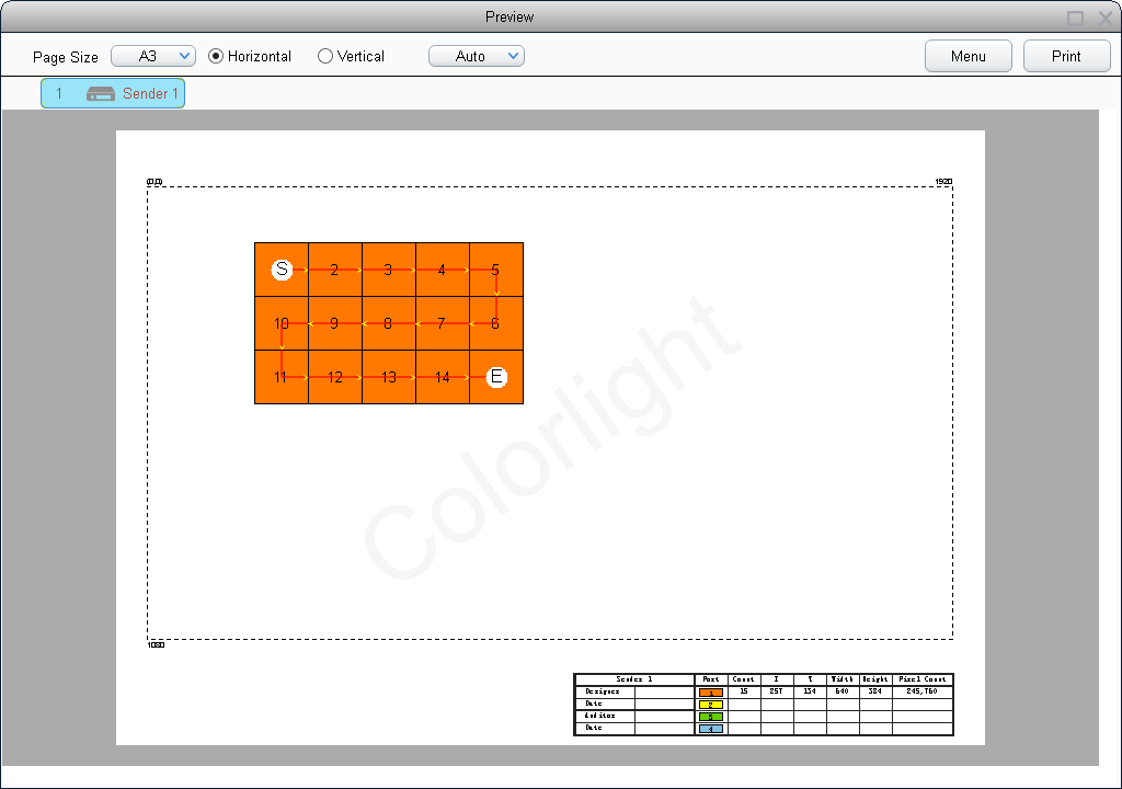
Image 4-19 Print Preview Window
The content of the Print Preview Window:
【Size of the Paper】iSet has the options of A3 or A4 paper sizes to choose from the drop-down list. When the paper size has been changed, the content on the list will auto-adjust based on the width of the paper.
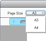
Image 4-20 Choose paper size
【Page Orientation】Choose horizontal or vertical of the page. After switching the orientation of the page, the displayed page orientation on the View Area and the cabinet information list remains unchanged, only scaling is changed.
【Scaling】The scaling of Print Preview can be adjusted. The scaling percentage options are: Auto, 25%, 50%, 75%,100%,125%,150%,175%,200%, use the Ctrl key + mouse wheel for scaling is supported, the default chosen scaling option is Auto.
【Menu】The content on the menu includes Save as Picture, Show Video Area, Watermark Settings, and Enable Binding.
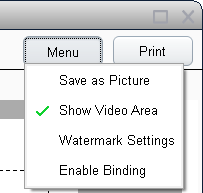
Image 4-21 Menu
- Save as Picture: Save the current printing drawing to the PC as picture. Support saving using suffixes of “.bmp”, “.png”, and “.jpg”. The default format is “.bmp”.
- Show Video Area: When checking Show Video Area, the video area under the current Sender resolution will be displayed; if cancel checking this option, the Print Preview Window will only show the layout of the cabinets of the current Sender.
- Watermark Settings: Watermark Setting supported. Watermark is default as Colorlight watermark in iSet. We can turn Watermark function on or off on the menu, we can also custom setting the content of the watermark.
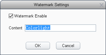
Image 4-22 Watermark Settings
- Enable Binding: After Binding is enabled, the whole Preview Page will slightly move to the right, and leave room for binding on the left.
【Print】Click on the Print button to print. “Print” supports using printer to print, as wells as transforming the contents being printed to word, pdf format.
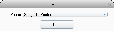
Image 4-23 Select Printers
Click on the button of drop-down option, to choose the manner of printing from the list. Based on the current installation environment of iSet, the supported Printers are different.
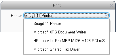
Image 4-24 List of Printers
【Information List】The information list is mainly displayed on the lower right corner of the View Area. The content includes Sender name, Port number, cabinet count, starting position of the cabinet (X, Y), width, height, and Pixel Count. On the first column on the left, Designer, Date, Auditor, and Date are displayed.
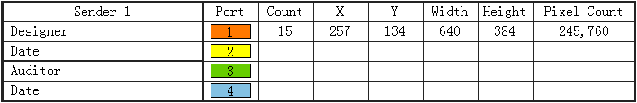
Image 4-25 Choose Printing List
- Undo
iSet will automatically record recent operation history, when a operation mistake happens, the users can correct the mistake using the Undo and Redo functions. Click on the “Undo” button to cancel the previous operation,Click the down triangle button on right side next to the“cancel”botton, from the list that pops up, to choose the operation that need to be canceled..
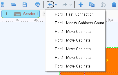
Image 4-26 Undo Function
- Redo
Restore to the status before undoing the operation, which is opposite to Undo.
- Add Cabinets
There are three steps to directly add cabinets in iSet: choose net ports, choose cabinet types, and add cabinets.
- Choose Net Ports: The senders have several net ports, first we choose Sender net ports that need cabinets to be added.
- Choose Cabinet Types: Choosing cabinet type falls into two categories: choosing cabinet types that are known, and choosing cabinet types that are unknown.
a) Choose cabinets of existing types: If the corresponding product type already exists in Type Management, directly choose to add cabinets of that product type.
b) Choose custom cabinet types: If the corresponding product type does not exist in Type Management, custom adding cabinets according to the actual size of the cabinets. Click “Add Cabinets”; choose “Custom Product”, input cabinet size.
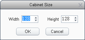
Image 4-27 Cabinet Size
- Add Cabinets: After choosing cabinet type, hold the left mouse button on the View Area and move the mouse, to add certain amount of cabinets.
- Copy
When a single cabinet or cabinet group has been chosen, click “Copy” or use shortcut key “Ctrl+C” to copy the parameters (including size and array of the cabinets) and mapping of the selected cabinets.
- Paste
Paste content of the copied cabinets to different ports or Senders. Only when the size of the cabinet is the same, can we use the paste function. If the copied cabinet or cabinet group already has an existing mapping, iSet will start pasting from the end of the copied cabinet or cabinet group.
- Delete Cabinets
Delete the chosen cabinets, and the mapping of the chosen cabinets at the same time.
- Clear Mapping
Click on the“Clear Mapping” button to clear all the mapping of all the cabinets at the current Sender’s Net Ports.
- Group
Choose multiple ungrouped cabinets, click the “Group” icon, to buildup a cabinet group; we can also build up a new cabinet group with multiple cabinets.
Choose a cabinet group, click on the “Ungroup” icon, we can ungroup this cabinet group.
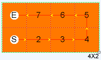
Image 4-28 Group
- Ungroup
iSet supports Ungroup function. When choosing a cabinet group, we can ungroup this group. After ungrouping, the chosen cabinet is default as first cabinet.
Support Multi-level Ungroup. When a cabinet group is within a cabinet group, after ungrouping, the cabinet group on the outer layer is ungrouped, but the cabinet group on the inner layer is not ungrouped.
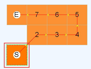
Image 4-29 Ungroup
- Normal
The Normal Mode is default to be selected in iSet. Under Normal Mode, we can perform operations on the cabinets, such as moving the positions of the cabinets, modifying the amount and size of cabinets.
- Move View
When the View Area is large, we can move the View, which is convenient the users to see. Click on the “Move View” button, the mouse will become hand-shaped on the View Area of the Design Page. Hold the left mouse button and move the mouse, the View Area will move according to the moving direction of the mouse.
- Manual Route
iSet supports Manual Routing, when choosing this mode, the mouse will become a paintbrush, choose the cabinets in the View Area to route. Click on the cabinets to route the cabinets on by one; we can also hold the left mouse button and move the mouse, to quickly route the cabinets.
When there is existing mapping in the cabinet group, if we need to cancel the routing of the routed cabinets, right-click on the routed cabinets, iSet will cancel the mapping of this cabinet and the following cabinets. If right-click on the cabinet at the beginning of the mapping, then we can clear the mapping of all cabinets.
- Highlight
We can highlight the cabinets in iSet. To locate the position of a certain cabinet, click on the “Highlight” button, and then click a cabinet in the View Area. At this time, the frames of the cabinet will display colors of red, white, blue, and green circularly.
The indicator light behind the highlighted cabinets will blink at a lower frequency than other cabinets, and if there is a LCD screen on the back of the cabinet, the LCD screen will display different colors.
After a certain cabinet has been highlighted, click other cabinets to highlight other cabinets. The cabinets that are chosen before will cancel highlighting. After the cabinets are highlighted, when clicking on the area outside of the cabinets, highlighting can be cancelled. Click on the “Normal” icon on Toolbar to cancel highlighting.
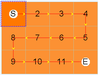
Image 4-30 Chosen Cabinets in View Area on the Design Page
- Scaling
Adjust the scaling percentages of the View Area of Design Page. Hold the Ctrl key, and then scale the View Area by scrolling the mouse wheel up and down.
Click on the drop-down box of scaling percentages on Toolbar, we can set the scaling percentages of the View Area.
When the focus of the mouse is on the View Area, hold the Ctrl key, and then scale the view by scrolling the mouse wheel up and down.
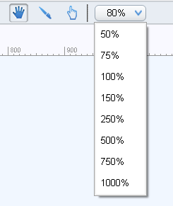
Image 4-31 Scaling
4.4.2 Information Column of Sender
iSet will show the Senders included in the current project under Toolbar, the Sender icon becomes gray when the Sender is offline, the Sender icon becomes bright when the Sender is online.
When the Sender is online, the contents displayed on the Sender icon are Sender Index, Sender icon identification, Sender name, Sender type, Delete.

At least one Sender is on the Sender Information Column. When there is only one Sender, cannot delete, the delete icon on the right will not show. iSet supports maximum of 15 Senders.
Chooe Sender
Click on Sender to choose the Sender as current Sender. The chosen Sender will display Sender Index, Type, Name, whether it has signal or not, etc. If the chosen as current Sender, only Sender Index and Sender Name will be shown.
- Add, Delete Sender
Click on the Delete button on the right of the Sender icon, to delete the current chosen Sender; Click on the “Add” button on the right of the Information Column, to add new Senders.
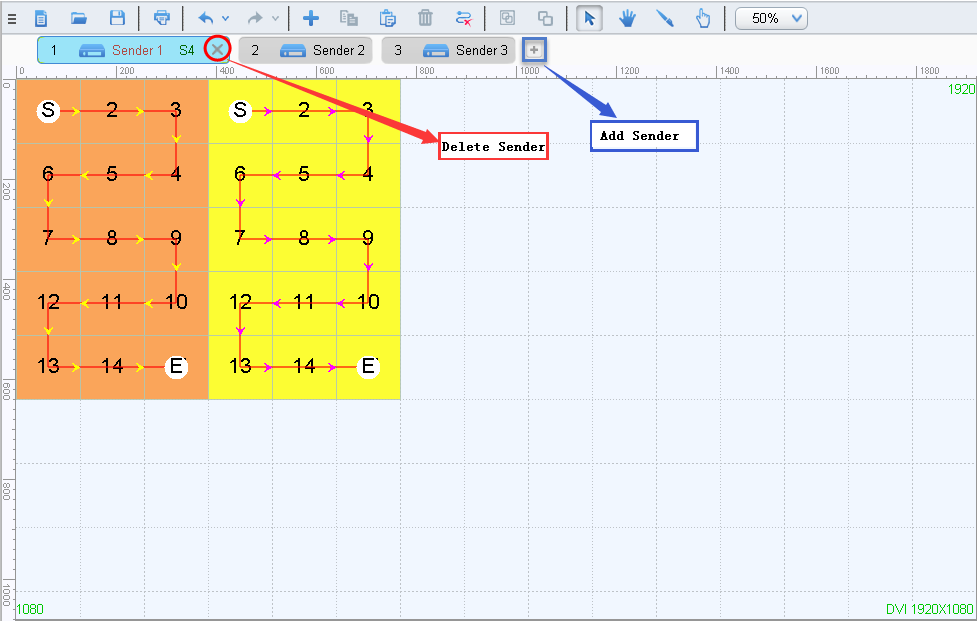
Image 4-32 Add, delete Sender
- Left Key Menu
Right click on the chosen Sender, a menu will pop up. According to the status and type of the Sender, the content on the context menu will be different. Click on the items on the context menu to operate.
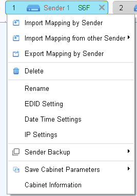
Image 4-33 Context Menu when Connecting Senders
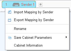
Image 4-34 Context Menu when Sender is not connected
- Import Cabinet Layout by Sender: Import Sender project file with suffix of “.sprj” from the PC, import the cabinet layout from the project file into the chosen Sender.
- Import Cabinet Layout by Other Sender: When there are two or more Senders, directly import the cabinet layout of other Senders into the current chosen Sender.
- Export Cabinet Layout by Sender: Save the related information of the current Sender as a Sender project file (.sprj file).
- Delete: Delete the current Sender, if only one Sender currently exists, then it cannot be deleted.
- Rename: Support renaming Senders to differentiate Senders. right-click on the Senders that need to be renamed, choose “Rename” on the menu, and directly input the names of the Senders into the popped-up window. Senders that are not renamed, the name will default as “Sender”.
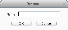
Image 4-35 Rename Senders
- EDID Setting: Set the EDID of the Sender, when the resolution of the sender has being displayed, the current sender resolution is default to display..
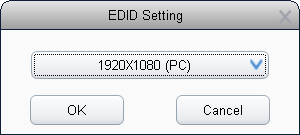
Image 4-36 Sender EDID
Click on the drop-down button to show the drop-down menu. Choose the pre-set resolution from the drop-down menu, we can also choose Custom.
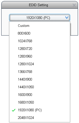
Image 4-37 Choose Sender Resolution
Set the width, height, and Frequency when custom modifying the Sender resolution.
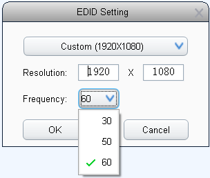
Image 4-38 Custom Sender Resolution
- MTU: Users can choose standard frame or long frame. When choosing standard frame, the signal can get through interchanger. When choosing long frame, the loading capacity of network is larger, but the signal cannot get through interchanger.
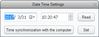
Image 4-39 Sender time
- Set IP Address: Click” Obtain an IP address automatically”, Sender will automatically obtain the assigned IP address. We can also manually set up IP address, subnet mask, and default gateway.
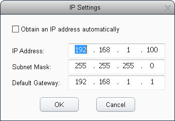
Image 4-40 Set up IP Address
- Mapping from Sender: Choose “mapping from Sender”, the mapping of cabinets will apply the mapping stored in the sender.
- LED Indicator light: turn the blinking of LED indicator light on or off.
- Sender Backup
When there are multiple senders being cascaded, this function can be chosen,to set a certain Sender as backups of the chosen Sender, the backup Sender will sync the information of the chosen Sender. All the net ports of the backup Sender will become backup Net port. There is a backup identification on the icon of the backup Sender.
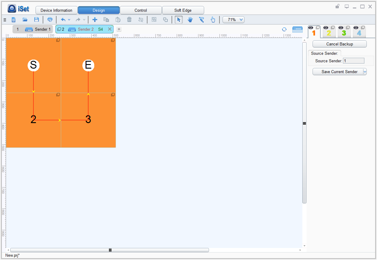
Image 4-41 Sender Backup
- Cancel Backup: Cancel backup of the Sender.
- Cabinet Type
iSet is default to turn on the function of saving cabinet parameters in Advanced functions. If this function does not appear in the right-click menu, then turn on the function of “saving cabinet parameters” in software functions after turning on advanced authorizations in the main menu of iSet. When saving cabinet parameters, have to assign the cabinet type of cabinets (choose cabinet and right-click, from the popped-up right-click menu, choose the assigned cabinet type from “cabinet parameters”). Before saving parameters, users can set the gamma value in the popped up window of “save cabinet parameters”.
Gray Out Unspecified: set the cabinets that have not been assigned cabinet type to gray.
Save Configurations: save the cabinet parameters of the chosen cabinet.
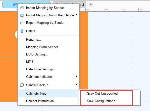
Image 4-42 Cabinets Type
- Cabinet Information
If cabinet information has been set in the cabinet parameter file, we can view cabinet information in iSet. Choose “Cabinet Information” from the Context Menu of Sender, iSet will pop up the “Cabinet Information” window, view the information of all the cabinets of the Sender on here.
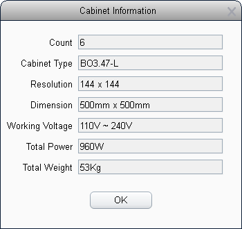
Image 4-43 Cabinet Information
- Detect Sender
Displayed on the right side of the Sender Information column, next to the“Sender Layout”icon, shown as refresh icon. Click to detect Sender.
- Sender Layout
When two or more Senders exist, the “Sender Layout” icon will show up on the right side of the Sender information column for setting the layout of the Sender.
Click on the Sender layout button, iSet will show the whole layout of the Sender.
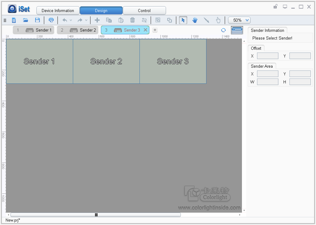
Image 4-44 Sender Layout Page
- We can adjust the arrangement of each Sender in the View Area by change the offset value or use the mouse to directly drag the Senders. The range of setting the offset of sender is: X(0-32768), Y(0-8192), We can also view the Sender area in the Sender Layout View.
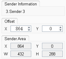
Image 4-45 Sender Information
- On the left is the View Area, all the background color of the Sender is green.
- Can only choose one Sender at a time.
- When the Sender is being selected, the frame of the Sender area is wrapped with solid yellow line, the background color fades.
- When Sender is overlapped, on the overlapping area, click on the Sender on the top layer, to choose the Sender on the next layer.
- View Designing Area
The View Designing Area is the major place for setting mapping, to achieve random placement settings for the cabinet mapping of all the net ports of a single Sender.
If the Sender has been connected with Video Input Signal, the size of the View Designing Area is the size of the video input signal connected with the Sender.
When no Sender has been connected in iSet or no video input has been connected to Sender, the default size of the Video Area is 1920*1080. If the size of the video input is not 1920*1080, we can choose “Video Area Settings” from the Context Menu of the Video Area. The Video Area Settings Window will pop up, check “Custom Video Area” to custom setting the video area.
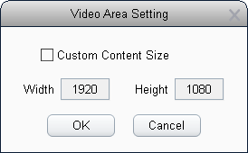
Image 4-46 Video Area Setting
Each Sender has an independent View Designing Area. Cabinets at different ports are represented by different colors. The cabinet colors at four net ports are red, yellow, green, and blue, when there are more than 4 netports, every 4 netports is one group, 4 colors will be displayed in sequence within the group. When the cabinet is over the video Area, it will show color of dark red.
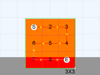
Image 4-47 Over Video Area Limit
On the lower right of the View Area, the Sender Resolution is shown. When video signal output cannot be detected in iSet, on the lower right corner of the View Area, it will show “No Signal” in iSet.
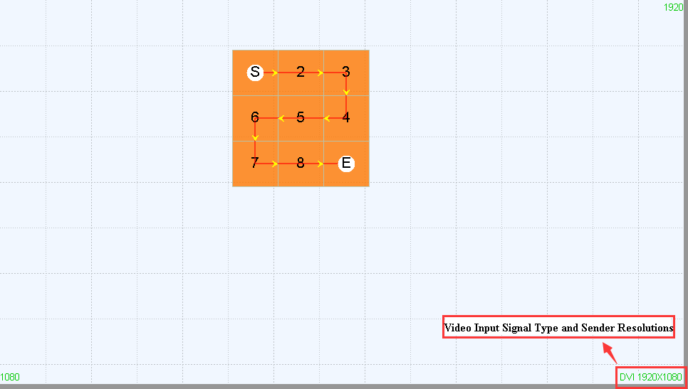
Image 4-48 Video Input Signal Type and Sender Resolutions
- Operations on Cabinets
- Choose Cabinets
Click on any cabinet within a cabinet group to select this group.
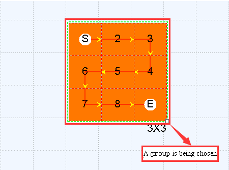
Image 4-49 A group is being chosen
To select a certain cabinet within a group, double-click on this cabinet within the cabinet group. We can also select multiple cabinets within the group at the same time: first select one cabinet within the group, and hold the Ctrl key, left-click to select other cabinets at the same time.
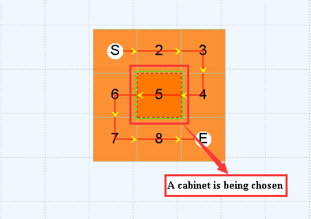
Image 4-50 A cabinet is being chosen
- Moving Cabinets
After choosing cabinets, we can use the mouse to directly move the position of the cabinets; we can also change the starting position from “Choose information” on the right side.
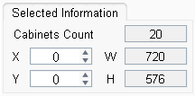
Image 4-51 Choose Information
iSet has the Attraction function. During dragging the cabinets, the cabinets will be automatically attracted to the nearby cabinets, and the ruler line. If the Attraction function is not needed, we can turn it off by unchecking “Enable Attraction” on the main menu.
- Set the Array of Cabinet Groups
Click on the cabinet group and hold the Ctrl key to choose it, at this time, on the lower right corner of the cabinet group a small box will show up, use the mouse to drag the small box, and set the array of the cabinets the same as the actual situation.
- Change Cabinet Amount
If there is no cabinet in the View Area, directly click on “Add Cabinets”, to add cabinets into the View Area.
If in the View Area the cabinets or cabinet groups have been added, and the cabinet groups are regular cabinet group, move the mouse to the border of the cabinet group, when the mouse has changed to double arrow, hold the mouse and drag to change the amount of cabinets, or users can hold the shift key, at this time, small boxes will show up around this cabinet group. meanwhile, drag the small boxes using the mouse, to change the amount of the cabinets.
When the chosen cabinet group is irregular, click on “Add Cabinets” button to add cabinets, or choose and delete the cabinet that need to be deleted..
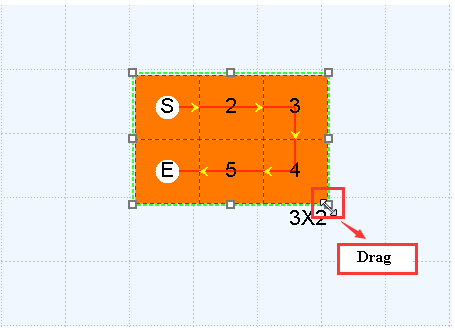
Image 4-52 Rapidly add or reduce Cabinets
- Context Menu
After choosing cabinets in the View Area, right-click, and the context menu will pop up. Click on the items on the Context Menu, to perform the corresponding shortcut key operation. Items on the Context Menu include: Undo, Redo, Ungroup, Select All, Cut, Copy, Delete Cabinets, Clear Mapping, Highlight, Cabinets Tpye, and Cabinet Information.
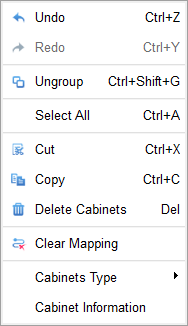
Image 4-53 Context Menu
Cabinets Type: Users can select the cabinet type of the cabinet and save the cabinet parameter, and can readback the cabinet parameters of the selected cabinets. When saving cabinet parameters, first choose the cabinet type of the cabinets that need to be saved. When read back the cabinet parameters, users have to choose a single cabinet in order to operate.
Gray Out Unspecified: set the cabinets that have not been assigned cabinet type to gray.
Select Same Type: choose all the cabinets that have the same cabinet type within the current net port.
Set Type: change the cabinet type of the chosen cabinet, users can choose the corresponding cabinet type from the drop-down menu of the popped up window (the pre-set cabinet types from the drop-down menu are cabinets types that are added from the “type management” of “add cabinets” on the side panel)
Save Configurations: save the cabinet parameters of the chosen cabinet.
Readback Cabinet Parameters: readback the cabinet parameters of the chosen cabinet. (This function can be used when choose a single cabinet)
Right-click on the blank space in the View Area, right-click, and the context menu will pop up. Click on the items on the Context Menu, to perform the corresponding shortcut key operation. Items on the Context Menu are: Undo, Redo, Select All, Clear Mapping, and Video Area Setting.
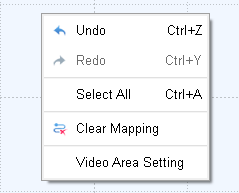
Image 4-54 Context Menu of Blank Space Area
The Parameter Setting Area mainly includes option of each port, Add Cabinets, Readback, Route, Sorting, Selected Information, Cabinet Size, Port Load Percent, Realtime Mapping, and Save Connection.
- Net Port Settings
- Show/Hide All Cabinet at Net Port
There is an “eye” icon on the upper left corner of every net port, when moving the mouse to the “eye” icon, a reminder of “Show or Hide All Cabinet at Net Port” will show up. Click on this icon, we can show or hide all the cabinets at Net Port. After the cabinets within the net port have been hidden, the parameter setting area of this net port cannot be changed.
- Lock/Unlock All Cabinet at Net Port
There is a “lock” icon on the upper right corner of every net port, a reminder of “Show or Hide All Cabinet at Net Port” will show. Click on this icon, we can lock or unlock the position of all the cabinets on the net port. When the position of the cabinet is locked, cannot move the position of the cabinet. In the parameter setting area, cannot add cabinets, readback parameters, change the information of the line and row, or information of the cabinet positions..
- Context Menu of Net Port
After choosing Net Port, right-click to pop up the Context Menu, the content on the Context Menu are: Import Mapping by Port, Export Mapping by Port, Port Backup, Cabinet Lock, Save Cabinet Parameters, and Cabinet Information.
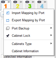
Image 4-55 Context Menu of Net Port
Choose the Net Port that needs mapping to be imported or exported. Right-click on the Net Port icon, choose “Import Layout by Port” or “Export Layout by Port” from the popped-up menu to import or export the mapping.
iSet can set backups between Sender’s net ports. For example, if we need to set Net Port 1 as the backup Port of Net Port 4, right-click on the icon of Net Port 4, and choose “Port Backup” from the popped-up menu, then choose Net Port 1.
Once a Net Port is set as Backups, a backup icon will show up on the upper right corner of the Backup Port, and backup-related information will show up on the right side of iSet.
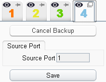
Image 4-56 Net Port Backup
Besides clicking on the lock icon on the upper right corner of the Net Port to lock or unlock the position of all the cabinets at Net Port, we can also choose Cabinet Lock from the Context Menu of the Net Port, to lock or unlock all the cabinets at Net Port. From the Context Menu of Net Port, we can also lock or unlock the position of all the cabinets of the Current Sender or the All Senders.
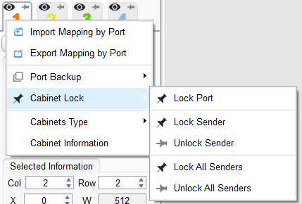
Image 4-57 Cabinet Lock
Cabinets Type: The function of saving cabinet parameters is default to be turned on in iSet, if this option does not appear on the right-click menu, then turn “saving cabinet parameters” on from the software functions after turning on Advanced Authorizations on the main menu of iSet. When saving cabinet parameters, the users need to assign the cabinet type of the cabinets first (to assign cabinet type, first choose the cabinet, then right click on the chosen cabinet, and choose the cabinet type from the “cabinet parameters” of the right-click menu.) Before saving the parameters, users can set the gamma value from the popped-up window of “saving cabinet parameters”.
Gray Out Unspecified: set all the cabinets that have not been assigned cabinet type to gray.
Save Configurations: save the cabinet parameters of all the cabinets loaded by the current net port.
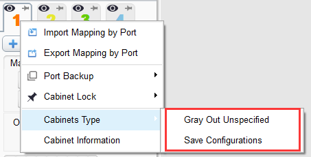
Image 4-58 Cabinets Type
Choose “Cabinet Information” from the Context Menu of Net Port, the information of all cabinets at the current net port can be viewed.
- Port Color and Switch
Every 4 ports is one group, port colors within the group will be different. The first port within the group will be red, the second port is yellow, the third is green, the forth is blue. The added cabinet colors from each port is the same as the color of the port.
The users can click on different port, and switch between different ports, the port being clicked becomes current port.
- Add Cabinets
Click on the “Add Cabinets” button, the menu will pop up. Add cabinets of existing types from the menu, or add custom cabinets. When adding custom cabinets, the width and height of the custom cabinets cannot exceed 1024.
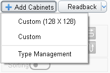
Image 4-59 Add Cabinets
Choose “Type Management” from the drop-down menu, to manage the product types from “Type Management”. On Type Management, we can manage all the product types.
Choose “Type Management” from the added cabinet menu, to enter the “Type Management” window. The tools in “Type Management” are:
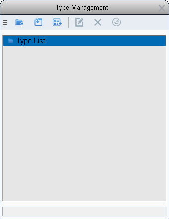
Image 4-60 Type Management
New Type Group:
Click on the “New Type Group” icon on toolbar to create a new type group.
Add Type Group:
Click on the “Add Type Group” icon on toolbar; choose the corresponding type group in the computer, to add a type group.
Add Product Type:
Click on the “Add Type” icon on toolbar; choose the corresponding type file in the computer, to add a product type.
Rename:
We can rename type groups or product types in Type Management.
Delete:
Click on the “Delete” icon on toolbar, to delete the selected type groups or product types.
Clear All:
Save the pre-set product types, to delete all the product types.
In addition, choose a product type or a type group in Type Management, right-click on it, choose “Export” from the Context Menu, to export the selected type groups as a folder, or export the selected product types as a product type file.
Please note that: the cabinet types that come with iSet are built in based on the LED screen manufacturers’ products, these parameter files cannot be deleted.
- Readback
Click on the “Readback” button, to readback cabinets. iSet default as reading back the cabinets at the current Net Port. Click the arrow button next to the Readback button; choose “Readback from Current Port”, “Readback from Current Sender”, and”Readback from All Senders”, “Readback From All Senders” option only appears when there are multiple senders being cascaded.
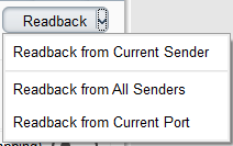
Image 4-61 Readback
- Route
Besides Manual Route, we can use the 8 pre-set patterns in iSet to quickly route the cabinets.
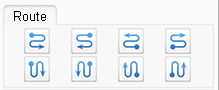
Image 4-62 Route
- Sorting
Open Sorting, the cabinets will show the sequence based on the actual cable connections of the screen.
- Choose Information
View the positions and size of the chosen cabinets, and adjust the starting positions of these cabinets.
- Cabinet Size
Adjust the width and height of the cabinet, the width or height cannot exceed the size of the cabinets in the parameters.
- Load Capacity at Net Port
To show the status of the load capacity of each Net Port, each Net Port is represented by an icon of a container. The scaling percentages on the right are 25%,50%,75%,100%。 Each Net Port can carry maximum of 655,360 pixels, when the Net Port load capacity does not exceed the limit, the Net Port shows green. When it exceeds the limit, the Net Port shows red.

Image 4-63 Load Capacity at Net Port
- Realtime Mapping
When Real-time Mapping has been enabled, the real-time effects can be seen in the screen when the Mapping has been changed.
- Save Connection
Save the mapping of the cabinet that we currently set, choose to Save Current Port, Save Current Sender, When there are multiple senders, the users can choose to Save All Senders.
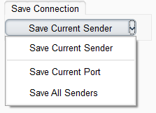
Image 4-64 Save Connection
The Control Setting is formed by several parts: Toolbar, View Designing Area, parameter setting area. This page is for setting the screen parameters of the Sender, which mainly are brightness, colors, test patterns, freeze, and black.
The content on Toolbar is: New Project, Open Project, Save Project, Normal, Move View, and Scaling.
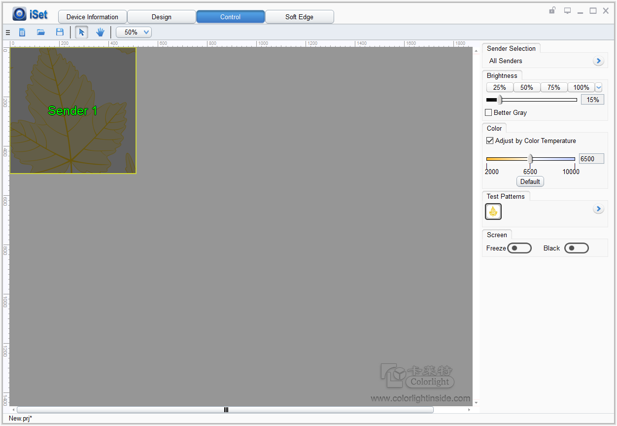
Image 4-65 View Designing Area
- Show Content
The content shown on the View Area indicates the amount of the Senders, load capacity, and the status of each Sender, which specifically are:
- The amount of Sender and the Load capacity: display based on the layout on the Design Page.
- Whether the Sender is online: if the Sender is offline, the corresponding area of the Sender is gray; if the Sender is online, based on its status (under Test Patterns, freeze screen, or Black screen), iSet will show the corresponding picture of on the corresponding area of the Sender.
- Whether the Sender has been chosen: Based on the color of the name of the Sender and its frame colors to distinguish them. The detail is: The frame color of the chosen Sender is yellow; the color of the Sender name is yellow or green. If the Sender has video signal input then it is green, otherwise it is yellow. The Senders that are not chosen have frame color of gray-black and the color of the Sender name is gray.
- On the lower right corner of the View Area shows watermark of Colorlight.
- Operations
(1)Under normal mode, click on a certain Sender, to choose or cancel choosing.
(2)Cannot cancel choosing the Sender that was chosen at last.
(3)The status of Sender being chosen is displayed on the right side of parameter setting interface at the same time.
- Choose Sender
This Setting module has three parts: Status of Sender being chosen, list of Senders, and Sender Selection.
- Status of Sender being chosen
To display which Senders have been chosen. Check all the Senders, shows “All Sender”; When only choose one Sender, display the Sender Index + Type + Name, such as “1.S2(Sender 1)”; When choosing 3 Senders or more, the Sender Index will be displayed, such as “1, 2, 3, 4”.
- Sender List
List all Senders, Online Sender will show Sender Index + Type + Name, such as “1.S2(Sender 1)”; Offline Sender will show Sender Index + Offline, such as “2. Not online”;
The status of Sender being chosen will be the same as what is drew on the View Area; cannot cancel the Sender last chosen.
- Sender Selection
Through the Sender Selection button, we can quickly choose the combination the Senders; we can set the combination of four Senders.
Put the mouse on Sender Selection, the Tip will inform the group name of the Sender and the index of the chosen Sender, such as “Group1 (1, 2)”.
Sender selection can be renamed and custom set from the drop-down menu.
Rename: Rename the Sender Selection.
Set: Reset the chosen Sender in the Sender group.
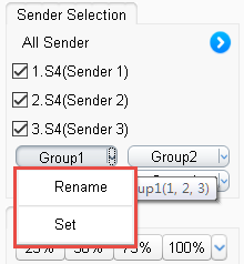
Image 4-66 Sender Group Rename and Setup
Choose a certain Sender group, when adjusting the parameters of the Sender, only adjust the Sender group. After choosing several Senders through Sender group, we can set the parameters in a batch.
- Brightness Adjustment
iSet supports Sender brightness adjustment. We can quickly set the brightness of the Senders by using the 4 pre-set buttons, or by using the slider (use the mouse to drag it or the left-right buttons). The brightness value of the 4 buttons can be customized, and the range is 0% to 100%.
We can set the Senders’ brightness value; we can also set Better Gray of the Sender. We can Turn Better Gray on to optimize the displaying results of the screen under low brightness.
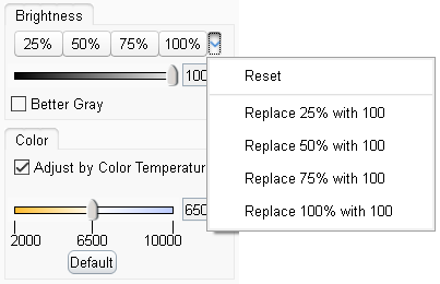
Image 4-67 Brightness Adjustment
- Color Adjustment
We can adjust the displaying results of the LED screen by setting color temperature. Use the mouse to slide the slider to set up color temperature. The adjustable range of color temperature in iSet is 2000-10000. Click on “Default”, we can quickly set up the color temperature to 6500.
If do not check the “Advanced Settings” option in iSet, we can also adjust the displaying results of the LED screen by setting the brightness of Red, Green, and Blue.
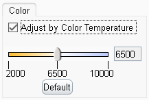
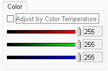
图4-68 Color Adjustment
- Video Source
Some Senders (such as S6F) is able to choose video signal source: HDMI and DVI. When the video signal source option is not matched with real situation, iSet will save the last frame of picture based on the settings of the Sender hardware, the picture on the screen remains still or black.
- Test Patterns
There are 22 types of Test Patterns. The pattern icon on the upper left is Normal; the pattern icon on the lower right is Automatic Cycle. S2 Sender does not support Automatic Cycle at this moment.
The users can set different test patterns based on their needs. Click on a certain test pattern icon, the Sender will show the corresponding test results. We can view the display of the screen through Test Pattern, and to detect and diagnose the screen.

Image 4-69 Test Patterns
- Screen
We can also set “Freeze” and “Black”. Click on “Freeze”, the picture on the screen will freeze; Click on “Black”, the screen will become black and display nothing.
After setting “Freeze” and “Black”, on the lower left corner of iSet, there will be red words as reminder. For all the online Senders, when the screen of the Sender is black, and the screen does not freeze, the words will show as “Black Screen”; when the screen of the Sender freezes, no black screen, the words will show as “Freeze”; when the function of “Black screen” and “Freeze Screen” of Sender, the words appear to be “Black Screen”.
After setting “Freeze” and “Black”, the cabinets on the Design page View Area will show the corresponding picture.
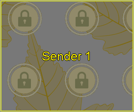
Image 4-70 Freeze Screen Status

Image 4-71 Black Screen Status
Soft Edge is fast fixing the seams between the modules or cabinets of the LED screens through cooperation of software, Sender, and Receiver Card.
The icons on the toolbar are: Import, Export, Select Seam, Select Cabinets, Seam Section, Normal, Move View, Scaling.

Image 4-72 Soft Edge Toolbar
- Import
Support importing calibration parameters, only support file with format of *.3fCoef. When importing, only support importing one Sender, but when there are multiple Senders, when importing calibration parameters, first users need to choose Sender.
- Export
Click on the export button, to export the calibration file of *.3fCoef to local. When exporting, only support exporting one Sender, but when there are multiple Senders, when exporting calibration parameters, first users need to choose sender.
- Select Seam
- Select a single seam
Use the mouse to click to choose a seam, normally choose the seams between the cabinets. When the modules are shown, choose the seams between the modules.
- Select multiple seams
Hold the Ctrl key, use the mouse to click to choose multiple seams, and can only choose the seams on the same row or line. Another way to choose multiple seams, use the mouse to click the ruler line, the users can choose the seams of the whole row or whole line at this position.
- Seam Section
After choosing the seam, click on “seam section” icon on toolbar, there are two circles on the chosen seam, move the position of the circle, to choose part of the seam.
- Select Cabinets
Click on a cabinet with the mouse to choose a cabinet; or click and drag an area with the mouse to choose multiple cabinets; or hold the Ctrl key and click on a cabinet with the mouse at the same time to choose a cabinet.
- Seam Section
Seam Section is effective only when performing seam compensations on seams. After turning Soft Edge mode on, choose the seams and click on the “Seam Section” on toolbar, or choose “Seam Section” from the right-click menu, or use the shortcut key “Ctrl+S”, at this time, there are two circles appear on the two sides of the chosen seam, one is green and the other is white.
The users can use the green circle to start changing the length of the seam. When moving the mouse to any circle and click, the circle will become green, click on this circle to move to adjust the length of the seam.
The seam section supports shortcut key operations: horizontal seams can be adjusted by“←”、“→”; Vertical seams can be adjusted by “↑”、“↓”; Click on the “tab” key to change the green circle. Click on anywhere else in the view to cancel seam section.
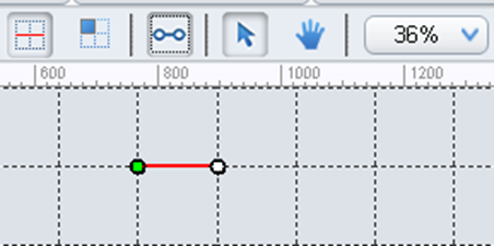
Image 4-73 Seam Section
- Move View
Users can move the displayed position of the cabinet for seam compensation in the View.
- Display scaling
Users can zoom in or zoom out the size of the view, maximum scaling is 1000%.
- View Area Display
The View Area is the main location for seam compensation. The frame of the View displays ruler lines. The edges of the cabinet are wrapped by relatively longer dash lines. In the cabinet, the modules are differentiated by relatively shorter dash lines. The cross line can position the current chosen Soft Edge area with the mouse.
Choose one side of the module or the edge of the cabinets, the chosen seam becomes red line. The seam compensation curve display box that pops up from the side is the seam compensation operating area, and there are 3 groups of add/minus buttons. Clicking the add/minus button on the left side is for doing more changes on the selected seam left area, the modification value of the right side gradually decreases. Clicking the add/minus button in the middle is for overall operations on modifications on the selected seam compensation area, with the increase and decrease. The right add/minus buttons are similar to the left add/minus buttons. The default standard is 1.0.
When a cabinet is chosen, the cabinet will become blue, and the frames of that cabinet become red.
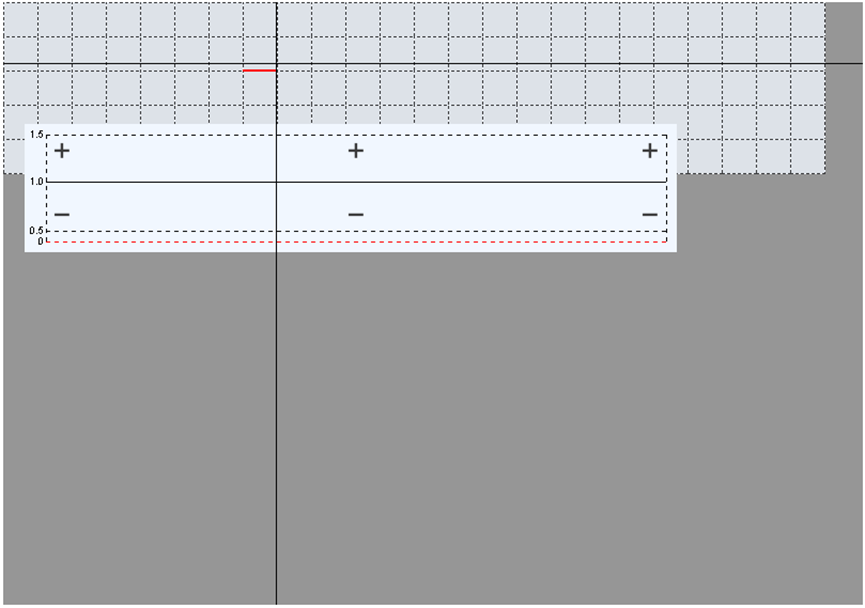
Image 4-74 Seam Compensation View Area
- Right-Click Menu
On the right-click menu of seam compensation view area, the following functions are included: a. Select Seam; b.Select Cabinet; c. Reset Selected Cabinet; d. Reset Selected Cabinet Edge; e. Seam Section (Ctrl+S); f. Import (Ctrl+I); g. Export (Ctrl+E); h. Reset All Seam .
Display different menus under different conditions:
- With normal mode, only menu f, g will be displayed; the import and export functions are the same as the import and exports functions in Toolbar.
- After entering seam compensation mode, under “Select Seam” mode, when no seam has been chosen, the menu will display a b f g, if a seam is chosen then e will appear.
- After entering seam compensation mode, under “Select cabinet” mode, when no cabinet has been chosen, the menu displays a b f g h, if one of the cabinets has been chosen, then c and d will appear.
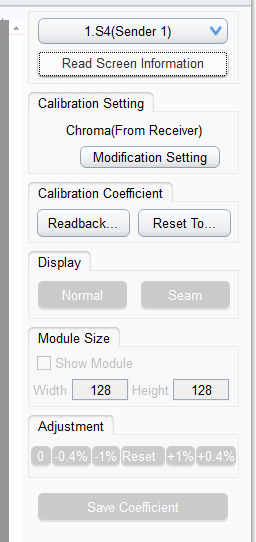
Image 4-75 Seam Compensation Parameters Settings Area
4.6.3 Seam Compensation Parameter Setting Area
- Choosing Sender
- Choosing Sender
iSet will display the Senders based on the amount of Senders on the Design Page. The amount of Senders on the Design page is the same as the Soft Edge Page. Only one Sender can be chosen when performing Soft Edge.
- Read Screen Information
Click on the “Read Screen Information” button, iSet will obtain the information of the current Sender and the connected Receiver Card.
- Calibration Setting
- Calibration Status
Display the current calibration status of the chosen sender, users can click “change settings” to switch to calibration status.
After turning calibration on, Soft Edge is on.
- Calibration Parameters
- Readback
Click on “Readback” button, choose “Readback from Receiver”, iSet will read the calibration parameters of the receiver card. If there are intelligent module, when clicking on the “Readback” button, there are two options: Readback from Receiver, Readback from Module. Choose “Readback from Receiver”, iSet will read the calibration parameters of the Receiver cards. Choose “Readback from Module”, iSet will read the calibration parameters of the module.
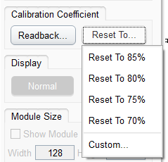
- Reset As
Before Soft Edge, first users need to lower the brightness of the LED screen, iSet default to have four brightness percentages 85%, 80%, 75%, and 70% to choose. Choose “Custom”, users can custom setting the scaling percentage of brightness.
- Display
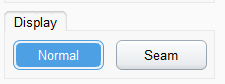
- Normal Mode
LED screen displays normal contents. Under normal mode, Soft Edge operations are not supported, and functions of module size settings, parameters adjustment, saving seam compensation parameters, undo and redo, choose seams or cabinets cannot be used.
- Soft Edge Mode
Under Soft Edge mode, soft edge operations are supported. Enter Soft Edge mode, the users will determine whether to open the calibration and seam compensation, if they are not turned on, then iSet will confirm whether to turn on Soft Edge.
The LED screen shows a white screen after entering the Soft Edge mode. Using functions of setting the size of module, coefficient adjustments, saving Soft Edge coefficients, undo and redo, choose seams or cabinets to perform Soft Edge.
Leaving the Soft Edge interface or close iSet will exit Soft Edge mode.
- Module Size
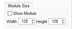
Image 4-78 Module Size
Check “show module”, input the height and width of the module, iSet will draw the modules on the cabinets in the View. Each modules are differentiated by gary hash lines. Only when the value of width and height of the cabinet can be divided by the value of width and height of the module, can the cabinets shows the modules.
- Adjustment
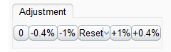
Image 4-79 Adjustment
iSet supports Soft Edge operations aiming at the chosen seams. There are 6 preset buttons, and are 0,-0.4%,-1%, reset(there is a dropdown button on the right that provides Soft Edge option),+1%,+0.4%.
When no seam has been chosen, the 5 coefficient adjustment buttons are gray and cannot be adjusted. When choosing a seam, click on seam coefficient button to perform soft edge fast, the results of soft edge will show on the LED screens in real time.
When choosing cabinets and the 5 coefficient adjustment buttons are gray and cannot be adjusted. Users can click the“reset” button to reset the soft Edge coefficients of the cabinets.
- Reset
“Reset”will set the Soft Edge coefficient to default value “1.0”. There are several cases for Reset:
① Reset the chosen seam: this option appears after choosing seams.
② Reset chosen cabinet: this option appears after choosing cabinets, reset coefficients of the chosen cabinets.
③ Reset edges of the chosen cabinets: this option appears after choosing cabinets, reset edge coefficients of the chosen cabinets.
④Reset all seams: Aiming at the chosen Sender, reset all the coefficients of all cabinets.
- Saving Coefficient
After Seam compensation adjustment has completed, click on the “Save Coefficient” button, users can save the modified parameters into the cabinets. After saving is successful, iSet will notify the users “Saving parameters is successful”
In iSet, we can set up Read Only mode on the Design、Control and Soft Edge Pages.
The read only mode is independent on different pages, and do not affect with each other.
On the page of Design, click on the” Read Only” button on the upper right corner of iSet to enter Read Only mode. Under Read Only mode, t The functions on the pages cannot be edited.
On the page of Control, click on the “Read Only” button on the upper right corner of iSet to enter read only mode. Under Read Only mode, The functions on the pages cannot be edited.
On the page of Soft Edge, click on the “read only”icon on the upper right corner of iSet, to enter read only mode. Under read only mode, users cannot enter soft edge mode. On the side panel, except for getting the screen information, other functions cannot be operated.
Read Only Mode supports memory function, after saving, create, close the current project, the status of Read Only Mode is not changed.
FAQS
Colorlight iset is mainly used to debug Colorlight’s control card and sending card, and supports the following models of Colorlight.
1. Support Windows/macOS/Linux platform.
2. Support for the processors of S7, K20, X16E, Z4(II), Z6 PRO-G2.
3. Support for the processors of X100-7U, Z8.
4. Support for the processors of X16 PRO, X12, X20.
5. Support for the Senders of X7, X2s, X4s.
6. Support the function of cabinet type with multi-receivers inside.
Colorlight iSet can run on Windows XP\Windows7\Windows8\Windows10\macOS operation systems.
Recommended minimal OS hardware configuration as below
⚫ CPU 2.0 GHZ;
⚫ RAM 1 GB;
⚫ Independent graphic card with 512MB memory
iSet function introduction
1.Device information page: mainly used to detect device information, such as detecting sending card information and detecting receiving card information.
2.Design page: mainly used to design the screen layout, such as designing the sending card layout and designing the cabinet layout.
3.Control page: mainly used to set the screen parameters of the sending card.
4.Seam repairing page: By adjusting the correction coefficient, repair the splicing gap between high-density screen cabinets and modules caused by processing and installation errors.