Description

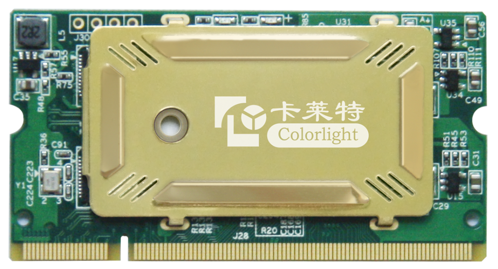
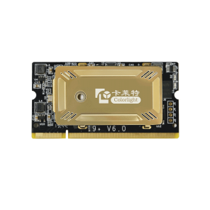
Colorlight i5 Receiving Card
i5 Receiving Card
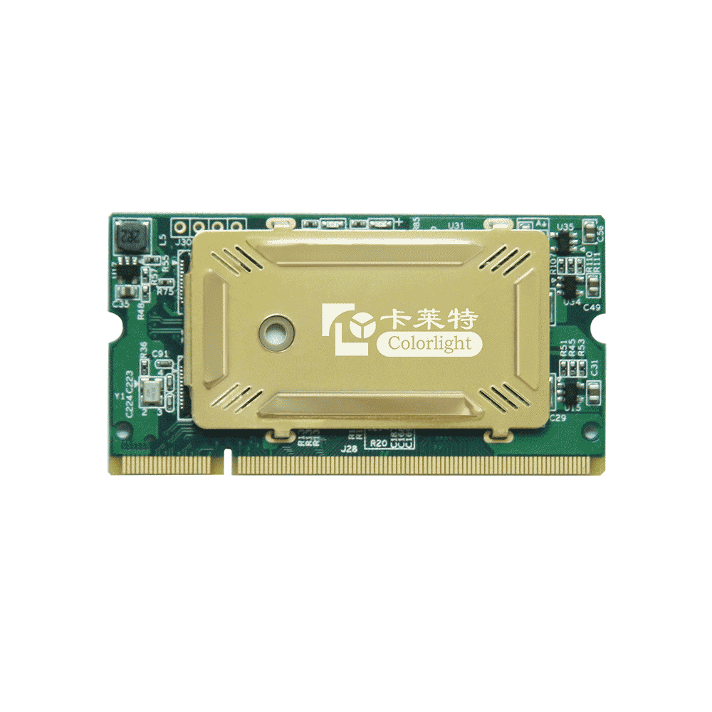
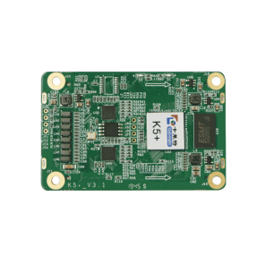
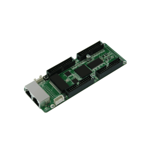
The Colorlight I5 Receiving card is a multi-function synchronization screen, and can make the clarity of the screen more sharply.Colorlight I5 Receiving card is one of the common accessories of LED display vendors,It mainly has the following features:
Features
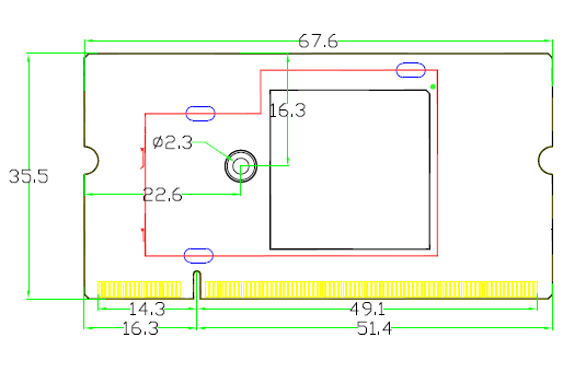
- Tiny size: 68*36mm, DDR2 SODIMM interface, easy for maintenance
- Support 32 groups of RGB signal output
- Loading capacity: 256*256 pixels
- High-precision point-by-point calibration in the brightness and chromaticity
- Support any scan mode from static to 1/32 scan
- Support wide working voltage of DC 3.3V-6V
Specifications
| Control system parameters | |
| Capacity | Full-color: 256*256 pixels |
| Cascade Control Area of the Largest Region | 65536*65536 pixels |
| Network Port Exchange | Supported, arbitrary use |
| Gray Level | Maximum 65536 levels |
| Display module compatibility | |
| Chip Supports | Supports conventional chips, PWM chips and other mainstream chips |
| Scan Mode | Two scanning methods to support refresh rate multiplier |
| Scan Type | Supports static sweep to 1/32 scan |
| Module Specifications Support | Supports 4096 pixels within any row, any column |
| Cable Direction | Supports route from left to right, from right to left, from top to bottom, from bottom to top |
| Data Sets | 32 RGB data sets |
| Data Folded | Supports 1~8 any discount to improve refresh rate |
| Data Exchange | 32 sets of data any exchange |
| Module Snapshot | Supports any pumping point |
| Compatible device and interface type | |
| Communication Distance | UTP cable≤140M
CAT6 cable≤170M OPTIC FIBER transmission distance unrestricted |
| Compatible Transmission Equipment | Gigabit switch, fiber transceiver, optional switches |
| Size | 68*36mm |
| Input Voltage | DC 3.3V~6V |
| Rated Current | 0.5A |
| Rated Power | 2.5W |
| Operating Temperature | -25℃~75℃ |
| Weight | 9.5g |
| Pixel level calibration | |
| Brightness Calibration | Supported |
| Chromaticity Calibration | Supported |
Hardware
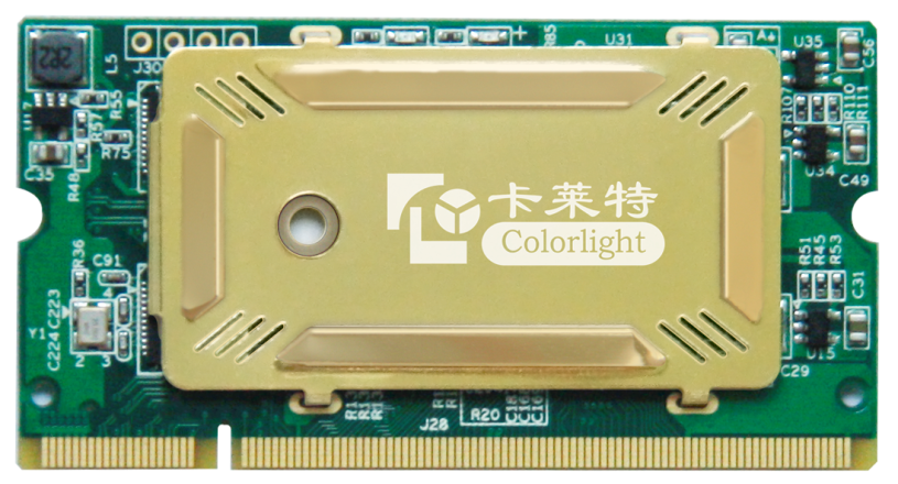
1, Interface
| S/N | Name | Function | Remarks |
| 1 | Signals indicator light | The indicator light flashes rapidly (about 5-10times/second) to show that the data signal transmission is normal | |
| 2 | Power indicator light | Red indicator light shows that the power supply is normal | |
| 3 | Fixed hole | Used to reinforce the receiving card to improve vibration resistance | |
| 4 | DDR interface | Connects with display’s HUB board or unit plate | From the diagram above, the left side of the guide plate is first pin (Viewing from the front of card) |
2, Figure for size and hole position
3, Definition of pins
| Instructions | Definition | Pin NO. | Definition | Instructions | |
| Ground Connection | GND | 1 | 2 | D5V | Power supply |
| GND | 3 | 4 | D5V | ||
| GND | 5 | 6 | D5V | ||
| GND | 7 | 8 | D5V | ||
| GND | 9 | 10 | D5V | ||
| GND | 11 | 12 | D5V | ||
| Do not connect | NC | 13 | 14 | NC | Do not connect |
| Network port 1 signal pin
Recommended use isolation transformer |
eth1_p1 | 15 | 16 | eth2_p1 | Network port 2 signal pin
Recommended use isolation transformer |
| eth1_n1 | 17 | 18 | eth2_n1 | ||
| NC | 19 | 20 | NC | ||
| eth1_n2 | 21 | 22 | eth2_n2 | ||
| eth1_p2 | 23 | 24 | eth2_p2 | ||
| NC | 25 | 26 | NC | ||
| eth1_p3 | 27 | 28 | eth2_p3 | ||
| eth1_n3 | 29 | 30 | eth2_n3 | ||
| NC | 31 | 32 | NC | ||
| eth1_n4 | 33 | 34 | eth2_n4 | ||
| eth1_p4 | 35 | 36 | eth2_p4 | ||
| Do not connect | NC | 37 | 38 | NC | Do not connect |
| Ground Connection | GND | 39 | 40 | GND | Ground Connection |
| Indicator light | LED_BTN_LED | 41 | 42 | A | Display control: 1. ABCDE for row decoding signal; 2. LED_LAT for signal lock;3. LED_OE control LED display enable, like a switch, it is GCLK when the led display use PWM chip; |
| Do not connect | NC | 43 | 44 | B | |
| NC | 45 | 46 | C | ||
| NC | 47 | 48 | D | ||
| Blanking | LED_CTRL | 49 | 50 | E | |
| The first CLK | LED_SCLK | 51 | 52 | LED_LAT | |
| Do not connect | NC | 53 | 54 | LED_OE | |
| Ground Connection | GND | 55 | 56 | GND | Ground Connection |
| RGB output | LED_R1 | 57 | 58 | LED_R2 | RGB output |
| LED_G1 | 59 | 60 | LED_G2 | ||
| LED_B1 | 61 | 62 | LED_B2 | ||
| LED_R3 | 63 | 64 | LED_R4 | ||
| LED_G3 | 65 | 66 | LED_G4 | ||
| LED_B3 | 67 | 68 | LED_B4 | ||
| LED_R5 | 69 | 70 | LED_R6 | ||
| LED_G5 | 71 | 72 | LED_G6 | ||
| LED_B5 | 73 | 74 | LED_B6 | ||
| LED_R7 | 75 | 76 | LED_R8 | ||
| LED_G7 | 77 | 78 | LED_G8 | ||
| LED_B7 | 79 | 80 | LED_B8 | ||
| LED_R9 | 81 | 82 | LED_R10 | ||
| LED_G9 | 83 | 84 | LED_G10 | ||
| LED_B9 | 85 | 86 | LED_B10 | ||
| LED_R11 | 87 | 88 | LED_R12 | ||
| LED_G11 | 89 | 90 | LED_G12 | ||
| LED_B11 | 91 | 92 | LED_B12 | ||
| LED_R13 | 93 | 94 | LED_R14 | ||
| LED_G13 | 95 | 96 | LED_G14 | ||
| LED_B13 | 97 | 98 | LED_B14 | ||
| LED_R15 | 99 | 100 | LED_R16 | ||
| LED_G15 | 101 | 102 | LED_G16 | ||
| LED_B15 | 103 | 104 | LED_B16 | ||
| Ground Connection | GND | 105 | 106 | GND | Ground Connection |
| GND | 107 | 108 | GND | ||
| RGB output | LED_R17 | 109 | 110 | LED_R18 | RGB output |
| LED_G17 | 111 | 112 | LED_G18 | ||
| LED_B17 | 113 | 114 | LED_B18 | ||
| LED_R19 | 115 | 116 | LED_R20 | ||
| LED_G19 | 117 | 118 | LED_G20 | ||
| LED_B19 | 119 | 120 | LED_B20 | ||
| LED_R21 | 121 | 122 | LED_R22 | ||
| LED_G21 | 123 | 124 | LED_G22 | ||
| LED_B21 | 125 | 126 | LED_B22 | ||
| LED_R23 | 127 | 128 | LED_R24 | ||
| LED_G23 | 129 | 130 | LED_G24 | ||
| LED_B23 | 131 | 132 | LED_B24 | ||
| LED_R25 | 133 | 134 | LED_R26 | ||
| LED_G25 | 135 | 136 | LED_G26 | ||
| LED_B25 | 137 | 138 | LED_B26 | ||
| LED_R27 | 139 | 140 | LED_R28 | ||
| LED_G27 | 141 | 142 | LED_G28 | ||
| LED_B27 | 143 | 144 | LED_B28 | ||
| LED_R29 | 145 | 146 | LED_R30 | ||
| LED_G29 | 147 | 148 | LED_G30 | ||
| LED_B29 | 149 | 150 | LED_B30 | ||
| LED_R31 | 151 | 152 | LED_R32 | ||
| LED_G31 | 153 | 154 | LED_G32 | ||
| LED_B31 | 155 | 156 | LED_B32 | ||
| Ground Connection | GND | 157 | 158 | GND | Ground Connection |
| Do not connect | NC | 159 | 160 | NC | Do not connect |
| NC | 161 | 162 | NC | ||
| NC | 163 | 164 | NC | ||
| NC | 165 | 166 | NC | ||
| NC | 167 | 168 | NC | ||
| NC | 169 | 170 | NC | ||
| NC | 171 | 172 | NC | ||
| NC | 173 | 174 | NC | ||
| NC | 175 | 176 | NC | ||
| NC | 177 | 178 | NC | ||
| NC | 179 | 180 | NC | ||
| NC | 181 | 182 | NC | ||
| NC | 183 | 184 | NC | ||
| NC | 185 | 186 | NC | ||
| NC | 187 | 188 | RCV_BK1 | ||
| NC | 189 | 190 | RCV_BK2 | ||
| NC | 191 | 192 | NC | ||
| NC | 193 | 194 | NC | ||
| NC | 195 | 196 | NC | ||
| NC | 197 | 198 | NC | ||
| Ground Connection | GND | 199 | 200 | GND | Ground Connection |

