Description


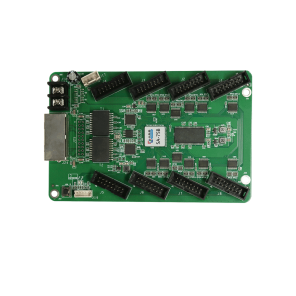
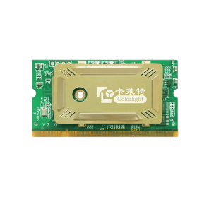
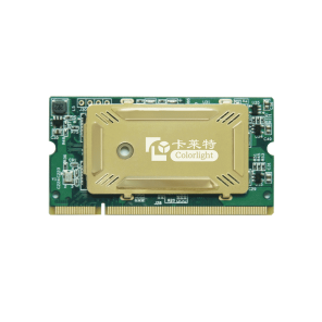
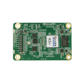
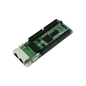
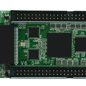
Colorlight N3 Mini Receiving Card
| Version | Release Date | Description |
| V1.0 | 2020-6-30 | First release |
Colorlight N3 Mini Receiving Card Features
- Loading capacity: 8192 pixels
- Supports 24 sets of RGB data serial output or 8 sets of RGB data parallel output
- Supports signal extension
- Supports brightness and chromaticity point-by-point calibration
- Supports any scan mode from static up to 1/16 scan
- Supports firmware backup and safe firmware upgrade
- Support loop backup
- Supports arbitrary offset of data group
- Supports the display image of single card to rotate 90, 180 or 270 degrees so as to achieve the display of special-shaped screen
- Signal transmission requires only 2 core twisted pair, and the peripheral cascade connection line supports going from one input to one output
- Fully enclosed design, effectively shielding electromagnetic wave, allowing the display to pass EMI testing
- Compatible with the relay card of Colorlight
Specifications
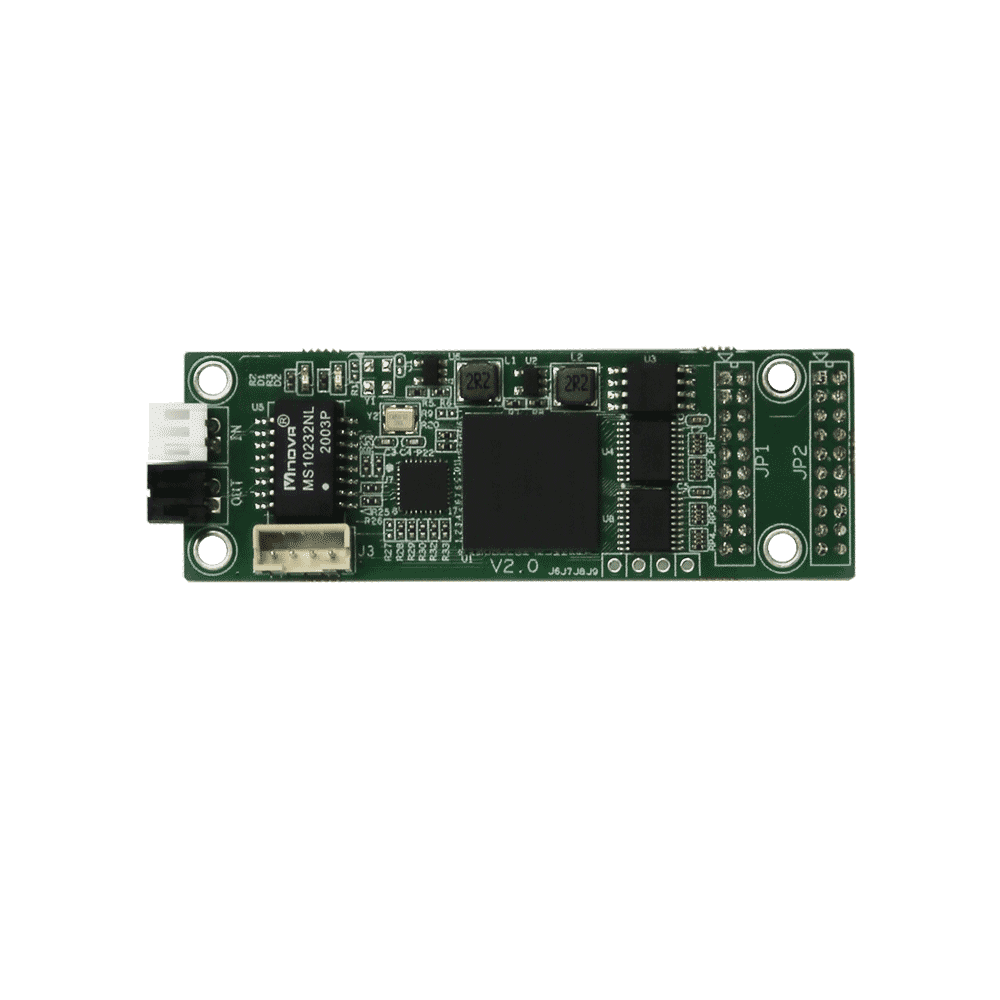
Hardware
| No. | Name | Function |
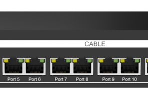
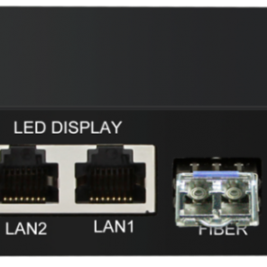
| 1 | Interface Type | 2×P2.0, for transmitting network signals, with no distinction between input and output |
| 2 | Data Interface | Used for power supply, outputting data and control signals such as CLK, LE and OE |
| 3 | 4pin Interface | Used for indicator light and test key |
Definition of Pins
- 8 sets of RGB parallel data mode. Pin No.15 and Pin No.16 on JP1 could be used as C and D for row decoding signal, or serial clock. Supports maximum 4 sets of serial clock extending within capacity.
- 24 sets of RGB serial data mode. Pin No.15 and Pin No.16on JP1 could be used as C and D for row decoding signal, or serial clock. Supports maximum 4 sets of serial clock extending within capacity.
| JP1 | |||||
| Instructions | Definition | Pin No | Definition | Instructions | |
| Power Supply | +5V | 1 | 2 | +5V | Power Supply |
| Ground Connection | GND | 3 Connection | 4 Connection | GND | Ground Connection |
| Data | DATA1 | 5 | 6 | DATA2 | Data |
| DATA3 | 7 | 8 | DATA4 | ||
| DATA5 | 9 | 10 | DATA6 | ||
| DATA7 | 11 | 12 | DATA8 | ||
| Clock | CLK1 | 13 | 14 | CLK2 | Clock |
| Clock / Row Decoding | CLK3/C | 15 | 16 | CLK4/D | Clock / Row Decoding |
| Latch | LE | 17 | 18 | OE | Output Enable |
| Row Decoding | A | 19 | 20 | B | Row Decoding |
| JP2 | |||||
| Instructions | Definition | Pin No. | Definition | Instructions | |
| Power Supply | +5V | 1 | 2 | +5V | Power Supply |
| Ground Connection | GND | 3 | 4 | GND | Ground Connection |
| Data | DATA9 | 5 | 6 | DATA10 | Data |
| DATA11 | 7 | 8 | DATA12 | ||
| DATA13 | 9 | 10 | DATA14 | ||
| DATA15 | 11 | 12 | DATA16 | ||
| DATA17 | 13 | 14 | DATA18 | ||
| DATA19 | 15 | 16 | DATA20 | ||
| DATA21 | 17 | 18 | DATA22 | ||
| DATA23 | 19 | 20 | DATA24 | ||
Statement
Thank you for purchasing the product of Colorlight (Shenzhen) Cloud Technology Co., Ltd. If you encounter any problems during use or have any suggestions, please contact us through official channels. We will do our best to provide support and listen to your valuable suggestions. We will constantly make improvements on technical specifications but without notice. You can visit www.colorlightinside.com to get more updated information.