Description

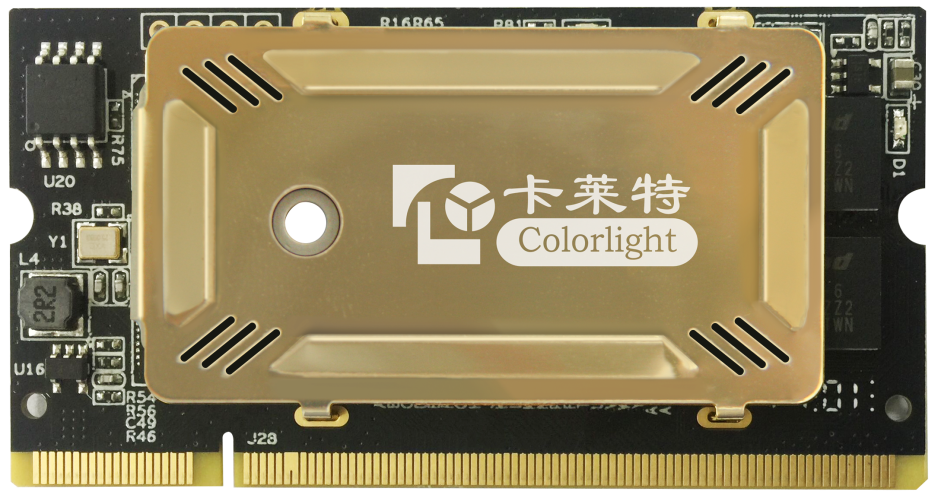
Colorlight i7 Receiving Card
i7 Receiving Card
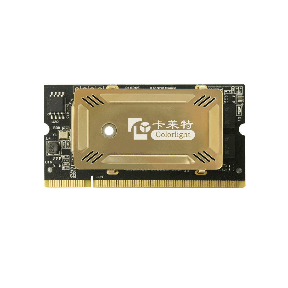
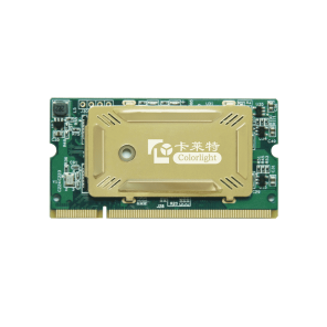
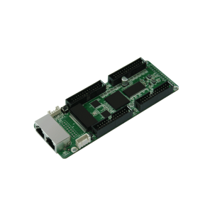
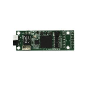
Colorlight i7 Receive Card is part of LED Display Control System. Colorlight I7 Receive Card is a high-end and universal receiver card specially introduced in color flash, with a small size, with 63 * 33mm; it uses DDR2 SODIMM interface to easily integrate into the line board or unit panel of the LED display, implement the LED display module High integration, which greatly promotes the design of the LED display unit and the structure.
Features
- Tiny size: 68*36mm, DDR2 SODIMM interface, easy for maintenance
- Support 32 groups of RGB signal output
- Loading capacity: 512*256 pixels
- Low latency
- Supports Auto-Calibration
- Seam compensation
- Support 3D display
- Improved grayscale performance at low brightness
- Smart panel marking good for maintenance
- Auto-recognizes sequence of connected receiver cards
- High-precision point-by-point calibration in the brightness and the chromaticity
- Supports smart module to save calibration coefficients and other information on module
- Temperature, humidity, power supply voltage monitoring on cabinet and fan rotating control
- Cable Detection
- Support LED point-by-point error detection of module
- Supports receiver card backup and power supply backup
- Various freeform display designs like spherical display, creative display, etc.
Specifications
| Control system parameters | |
| Sending device | All of Colorlight’s sending devices |
| Capacity | Full-color: 512*256 Pixels |
| Network Port Exchange | Supported, arbitrary use |
| Gray Level | Maximum 65536 Levels |
| Display module compatibility | |
| Chip Supports | Supports conventional chips, PWM chips, lighting chips and other mainstream chips. |
| Scan Mode | Two scanning methods to support refresh rate multiplier |
| Scan Type | Supports static sweep to 1/32 scan |
| Module Specifications Support | Supports 4096 pixels within any row, any column |
| Cable Direction | Supports route from left to right, from right to left, from top to bottom, from bottom to top. |
| Data Sets | 32 RGB data sets |
| Data Folded | Supports 1~8 any discount to improve refresh rate. |
| Data Exchange | 32 sets of data any exchange |
| Module Snapshot | Supports any pumping point |
| Compatible device and interface type | |
| Communication Distance | UTP cable≤140M
CAT6 cable≤170M OPTIC FIBER transmission distance unrestricted |
| Compatible with Transmission Equipment | Gigabit switch, fiber transceiver, optical switches. |
| Size | 67.6*35.5mm |
| Input Voltage | DC 3.3V~6V |
| Rated Current | 0.5A |
| Rated Power | 2.5W |
| Storage and Transport Temperature | -50℃~125℃ |
| Operating Temperature | -25℃~75℃ |
| Body Static Resistance | 2KV |
| Weight | 9.5g |
| Monitoring function (in conjunction with multi-function card) | |
| Temperature Monitoring | Cabinet temperature monitoring between -25℃ ~ 75℃
1 port for each card |
| Humidity Monitoring | One port to monitor receiver card humidity range with 20% ~ 95%
1 port for each card |
| Bit Error Monitoring | Monitoring the total number of data packets and error rate to check network quality |
| Supply Voltage Monitoring | 5 ports for supply voltage monitoring |
| Full Color LCD Display Panel | Supports full color LCD display panel |
| Pixel level calibration | |
| Brightness Calibration | Supported |
| Chromaticity Calibration | Supported |
| Other features | |
| Hot Backup | Supports loop backup, double sender backup, double receiver card backup and double power supply backup |
| Shaped Screen | Supports various freeform display, spherical display, creative display, etc. through the data arbitrary offset |
| Program Backup | Proprietary redundant firmware backup on card no matter how to use, upgrade, send parameters, continuous functionality |
Hardware
- Interface
| S/N | Name | Function | Remarks |
| 1 | Signals indicator light | The indicator light flashes rapidly (about 5-10times/second) to show that the data signal transmission is normal | |
| 2 | Power indicator light | Red indicator light shows that the power supply is normal | |
| 3 | Fixed hole | Used to reinforce the receiving card to improve vibration resistance | |
| 4 | DDR interface | Connects with display’s HUB board or unit plate | From the diagram above, the left side of the guide plate is first pin (Viewing from the front of card) |
- Figure for size and hole position
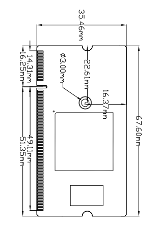
colorlight i7 Receiving Card circuit board
- Definition of Pins
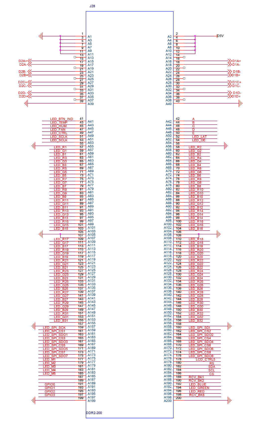
colorlight i7 Receiving Card Pin Circuit Link Example Diagram
- Definition of Pins
| Instructions | Definition | Pin No. | Definition | Instructions | |
| Ground connection | GND | 1 | 2 | D5V | Power supply |
| GND | 3 | 4 | D5V | ||
| GND | 5 | 6 | D5V | ||
| GND | 7 | 8 | D5V | ||
| GND | 9 | 10 | D5V | ||
| GND | 11 | 12 | D5V | ||
| Do not connect | NC | 13 | 14 | NC | Do not connect |
| Network port 1 signal pin
Recommended use isolation transformer |
eth1_p1 | 15 | 16 | eth2_p1 | Network port 2 signal pin
Recommended use isolation transformer |
| eth1_n1 | 17 | 18 | eth2_n1 | ||
| NC | 19 | 20 | NC | ||
| eth1_n2 | 21 | 22 | eth2_n2 | ||
| eth1_p2 | 23 | 24 | eth2_p2 | ||
| NC | 25 | 26 | NC | ||
| eth1_p3 | 27 | 28 | eth2_p3 | ||
| eth1_n3 | 29 | 30 | eth2_n3 | ||
| NC | 31 | 32 | NC | ||
| eth1_n4 | 33 | 34 | eth2_n4 | ||
| eth1_p4 | 35 | 36 | eth2_p4 | ||
| Do not connect | NC | 37 | 38 | NC | Do not connect |
| Ground connection | GND | 39 | 40 | GND | Ground connection |
| Indicator light | LED_BTN_LED | 41 | 42 | A | Display control: 1. ABCDE for row decoding signal; 2. LED_LAT for signal lock; 3. LED_OE control LED display enable, like a switch, it is GCLK when the led display use PWM chip; |
| Temperature
monitoring |
LED_TEMP | 43 | 44 | B | |
| Humidity monitoring | LED_HUM | 45 | 46 | C | |
| Fan control | LED_FAN | 47 | 48 | D | |
| Blanking | LED_CTRL | 49 | 50 | E | |
| CLK | LED_SCLK | 51 | 52 | LED_LAT | |
| LED_SCLK | 53 | 54 | LED_OE | ||
| GND | 55 | 56 | GND | ||
| RGB output of part A: A total of 8 groups of RGB, corresponding with LED_SCLK | LED_R1 | 57 | 58 | LED_R2 | RGB output of part B: A total of 8 groups of RGB, corresponding with LED_SCLK |
| LED_G1 | 59 | 60 | LED_G2 | ||
| LED_B1 | 61 | 62 | LED_B2 | ||
| LED_R3 | 63 | 64 | LED_R4 | ||
| LED_G3 | 65 | 66 | LED_G4 | ||
| LED_B3 | 67 | 68 | LED_B4 | ||
| LED_R5 | 69 | 70 | LED_R6 | ||
| LED_G5 | 71 | 72 | LED_G6 | ||
| LED_B5 | 73 | 74 | LED_B6 | ||
| LED_R7 | 75 | 76 | LED_R8 | ||
| LED_G7 | 77 | 78 | LED_G8 | ||
| LED_B7 | 79 | 80 | LED_B8 | ||
| LED_R9 | 81 | 82 | LED_R10 | ||
| LED_G9 | 83 | 84 | LED_G10 | ||
| LED_B9 | 85 | 86 | LED_B10 | ||
| LED_R11 | 87 | 88 | LED_R12 | ||
| LED_G11 | 89 | 90 | LED_G12 | ||
| LED_B11 | 91 | 92 | LED_B12 | ||
| LED_R13 | 93 | 94 | LED_R14 | ||
| LED_G13 | 95 | 96 | LED_G14 | ||
| LED_B13 | 97 | 98 | LED_B14 | ||
| LED_R15 | 99 | 100 | LED_R16 | ||
| LED_G15 | 101 | 102 | LED_G16 | ||
| LED_B15 | 103 | 104 | LED_B16 | ||
| Ground connection | GND | 105 | 106 | GND | Ground connection |
| GND | 107 | 108 | GND | ||
| RGB output of part C : A total of 8 groups of RGB, corresponding with LED_SCLK
It can become part A’s check back and circuit signal detection of return |
LED_R17 | 109 | 110 | LED_R18 | RGB output of part D : A total of 8 groups of RGB, corresponding with LED_SCLK
It can become part A’s check back and circuit signal detection of return |
| LED_G17 | 111 | 112 | LED_G18 | ||
| LED_B17 | 113 | 114 | LED_B18 | ||
| LED_R19 | 115 | 116 | LED_R20 | ||
| LED_G19 | 117 | 118 | LED_G20 | ||
| LED_B19 | 119 | 120 | LED_B20 | ||
| LED_R21 | 121 | 122 | LED_R22 | ||
| LED_G21 | 123 | 124 | LED_G22 | ||
| LED_B21 | 125 | 126 | LED_B22 | ||
| LED_R23 | 127 | 128 | LED_R24 | ||
| LED_G23 | 129 | 130 | LED_G24 | ||
| LED_B23 | 131 | 132 | LED_B24 | ||
| LED_R25 | 133 | 134 | LED_R26 | ||
| LED_G25 | 135 | 136 | LED_G26 | ||
| LED_B25 | 137 | 138 | LED_B26 | ||
| LED_R27 | 139 | 140 | LED_R28 | ||
| LED_G27 | 141 | 142 | LED_G28 | ||
| LED_B27 | 143 | 144 | LED_B28 | ||
| LED_R29 | 145 | 146 | LED_R30 | ||
| LED_G29 | 147 | 148 | LED_G30 | ||
| LED_B29 | 149 | 150 | LED_B30 | ||
| LED_R31 | 151 | 152 | LED_R32 | ||
| LED_G31 | 153 | 154 | LED_G32 | ||
| LED_B31 | 155 | 156 | LED_B32 | ||
| Ground connection | GND | 157 | 158 | GND | Ground connection |
| Save correction coefficients in module | LED_SPI_SCK | 159 | 160 | LED_SPI_SDI | Save correction coefficients in module |
| LED_SPI_CS1 | 161 | 162 | LED_SPI_CS2 | ||
| LED_SPI_SDO1 | 163 | 164 | LED_SPI_SDO2 | ||
| LED_SPI_CS3 | 165 | 166 | LED_SPI_CS4 | ||
| LED_SPI_SDO3 | 167 | 168 | LED_SPI_SDO4 | ||
| LED_SPI_CS5 | 169 | 170 | LED_SPI_CS6 | ||
| LED_SPI_SDO5 | 171 | 172 | LED_SPI_SDO6 | ||
| LED_SPI_CS7 | 173 | 174 | LED_SPI_CS8 | ||
| LED_SPI_SDO7 | 175 | 176 | LED_SPI_SDO8 | ||
| Extended functional interface for customized features | LED_M1 | 177 | 178 | LCD_CTRL5 | The interface to connect LCD display |
| LED_M2 | 179 | 180 | RS | ||
| LED_M3 | 181 | 182 | SDA | ||
| LED_M4 | 183 | 184 | SCL | ||
| LED_M5 | 185 | 186 | CS | ||
| Do not connect | NC | 187 | 188 | RCV_BK1 | Vacant signal for double backup receiving card |
| NC | 189 | 190 | RCV_BK2 | ||
| LCD | GPIO0 | 191 | 192 | LED_BLUE | RGB tricolor indicator |
| GPIO1 | 193 | 194 | LED_GREEN | ||
| GPIO2 | 195 | 196 | LED_RED | ||
| GPIO3 | 197 | 198 | RCV_BK6 | Do not connect | |
| Ground connection | GND | 199 | 200 | GND | Ground connection |

