Description

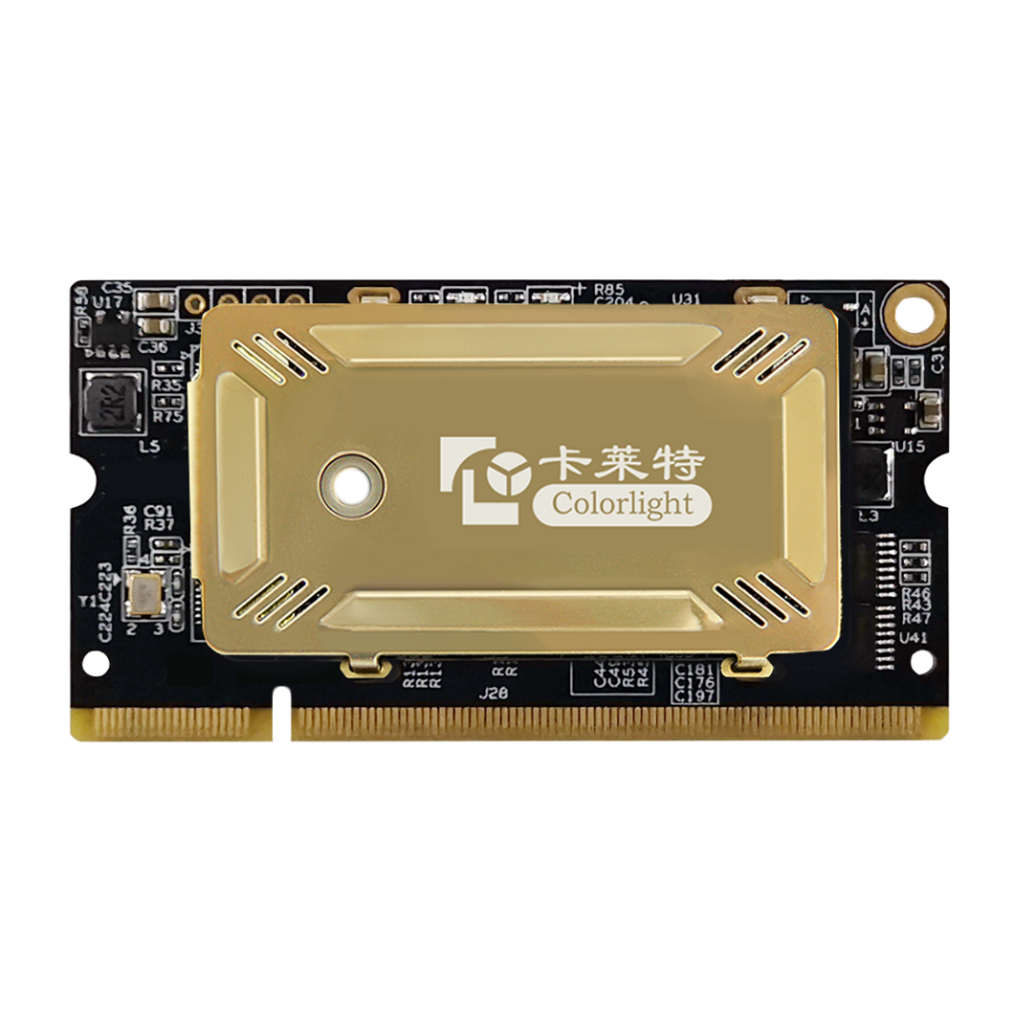
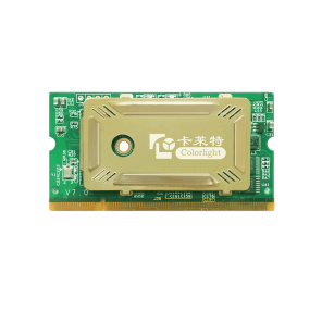
Colorlight i9 Receiving Card
i9 Receiving Card
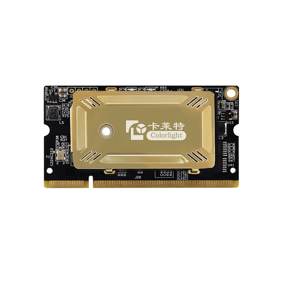
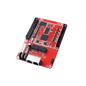
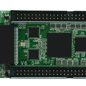
Colorlight i9 Receive Card is part of LED Display Control System. Colorlight I9 Receive Card is a high-end and universal receiver card specially introduced in color flash, with a small size, with 67.6×35.46mm; Colorlight i9 Receiving Card uses DDR2 SODIMM interface to easily integrate into the line board or unit panel of the LED display, implement the LED display module High integration, which greatly promotes the design of the LED display unit and the structure.
Features
- Tiny size: 67.6×35.46mm, DDR2 SODIMM interface, easy for maintenance
- Supports HDR
- Supports 32 sets of RGB signal parallel output
- Loading capacity: 384*256 pixels
- Supports brightness and chromaticity point-by-point calibration with 14bit accuracy
- Improved grayscale performance at low brightness
- Supports color temperature and gamut adjustment
- Supports highlight and sorting
- Seam compensation
- Low latency
- Fast upgrades and fast send out calibration coefficients
- Supports smart module to save calibration coefficients and other information on module
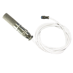
- Temperature, humidity, power supply voltage monitoring on cabinet and fan control
- Supports LED point-by-point error detection of module
- Supports LCD panel display
- Supports dual card backup and dual power backup
- Supports any scan mode from static to 64 scan
- Supports any pumping point, and realize creative displays like shaped display, spherical display, etc.
- Compatible with all series of Colorlight sending devices
Specifications
| Control System Parameters | |
| Sending Device | All series of Colorlight sending devices |
| Capacity | Full-color: 384*256 pixels |
| Network Port Exchange | Supported, arbitrary use |
| Gray Level | Maximum 65536 levels |
| Display Module Compatibility | |
| Chip Supports | PWM chips |
| Scan Type | Supports any scan type from static to 64 scan |
| Module Specifications Support | Supports 8192 pixels within any row, any column |
| Cable Direction | Supports route from left to right, from right to left, from top to bottom, from bottom to top |
| Data Sets | 32 sets of parallel RGB full color data, 64 sets of serial RGB data |
| Data Folded | Supports 2~4 any discount to improve refresh rate |
| Data Exchange | 32 sets of data any exchange |
| Module Snapshot | Supports any pumping point |
| Compatible Device and Interface Type | |
| Communication Distance | UTP cable ≤ 140M
CAT6 cable ≤ 170M Optic fiber transmission distance unrestricted |
| Compatible with Transmission Equipment | Gigabit switch, fiber transceiver, optical switches |
| Size | 67.6*35.46mm |
| Input Voltage | DC 3.3V~6V |
| Rated Current | 0.5A |
| Rated Power | 2.5W |
| Storage and Transport Temperature | -50℃~125℃ |
| Operating Temperature | -25℃~75℃ |
| Body Static Resistance | 2KV |
| Weight | 9.5g |
| Monitoring Function (in conjunction with multi-function card) | |
| Temperature Monitoring | Cabinet temperature monitoring between -25℃~ 75℃
1 port for each card |
| Humidity Monitoring | Receiver card humidity monitoring between 20% ~ 95%
1 port for each card |
| Bit Error Monitoring | Monitors the total number of data packets and error packets to check network quality |
| Supply Voltage Monitoring | 5 ports for supply voltage monitoring |
| Full Color LCD Display Panel | Supported |
| Pixel Level Calibration | |
| Brightness Calibration | Supported |
| Chromaticity Calibration | Supported |
| Other Features | |
| Hot Backup | Supports loop backup, dual sender backup, dual receiver card backup and dual power supply backup |
| Shaped Screen | Supports various freeform display, spherical display, creative display, etc. |
| Program Backup | Proprietary redundant firmware backup on card no matter how to use, upgrade, send parameters, continuous functionality |
Hardware
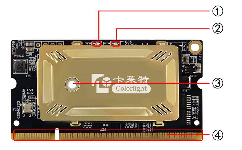
1, Interface
| S/N | Name | Function | Remarks | |
| 1 | Signal indicator light | Flashes once per second | Receiving card: normal working,
Network cable connection: normal |
|
| Flashes 10 times per second | Receiving card: normal working,
Cabinet: Sorting & Highlight |
|||
| Flashes 4 times per second | Receiving card: Backing up senders(Loop Bcakup status) | |||
| 2 | Power indicator light | The red indicator light shows that the power supply is normal | ||
| 3 | Fixed hole | Used to reinforce the receiving card to improve vibration resistance | ||
| 4 | DDR interface | Connects with display’s HUB board or unit plate | From the diagram above, the left side of the guide plate is first pin (Viewing from the front of card) | |
2, Definition of Pins
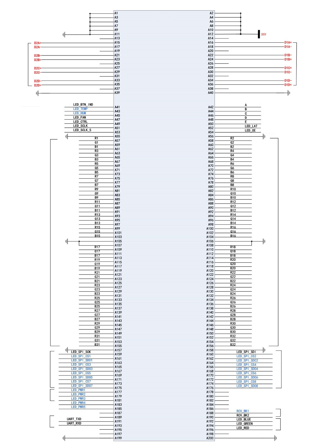
Colorlight i9 Receiving Card Pin Circuit Link Example Diagram
3, Description of Pins

