Description


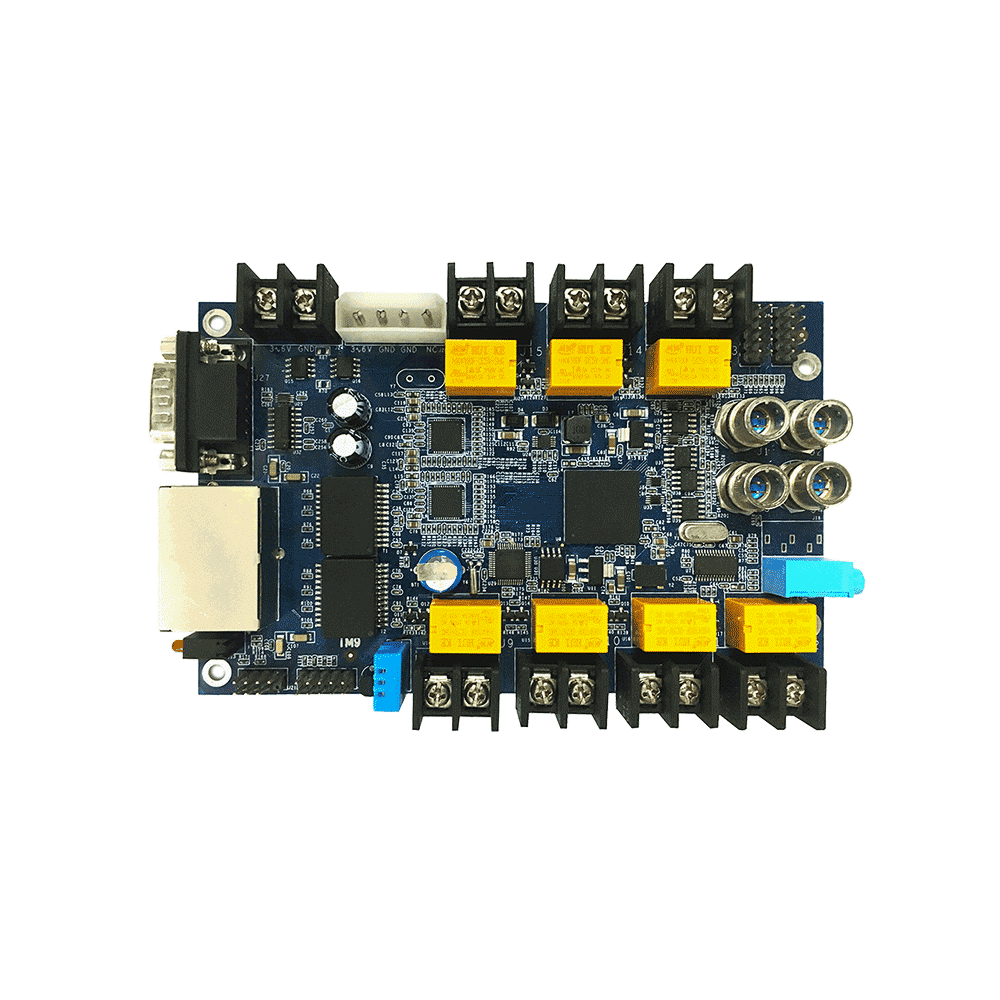
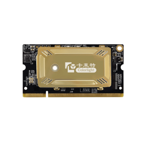
colorlight iM9 Multifunction Card
iM9 Multifunction Card
Overview
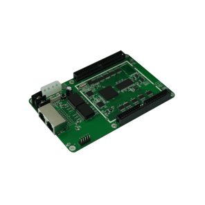
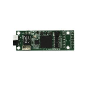
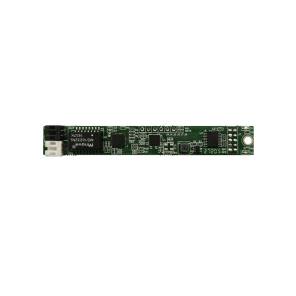
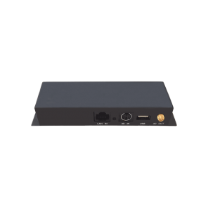
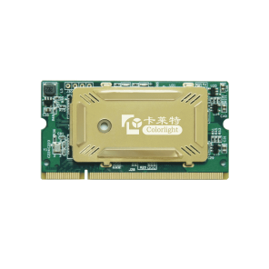
colorlight iM9 Multifunction Card multifunction card is an important accessories of the Colorlight control system for environmental monitoring and remote control.
iM9 can be used to monitor the operating environment of the LED displays, such as temperature, humidity, smoke, etc., to ensure the safety of the display.
iM9 can detect the environmental brightness and adjust the brightness of the display automatically in order to make sure the display work in the most suitable brightness.
iM9 contains 7 Relays Switches that can be used to control the power supply remotely. Benefit from iM9, you can turn on or off the power supply of the equipments such as display, air conditioning, fans, and power distribution cabinets by the software on the computer, instead of going to the front of the equipments.
Specifications
| System compatibility | |
| Sending device | C series Sender, Z series Sender, S series Sender, etc. |
| Receiving device | All Series of Colorlight Receiving Card |
| Transmission equipment | Support Gigabit switch, Fiber Converter |
| Physical/Electrical | |
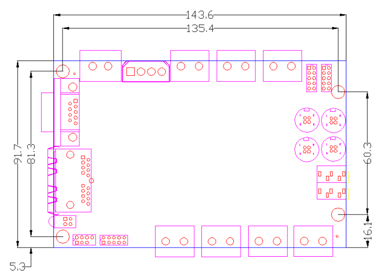
| Size | 143*93mm |
| Power input | DC 3.3~6V supply voltage |
| Power consumption | 4.65W |
| Weight | 138g |
| Remote Control | |
| Remote power management | 4 switches for LED display
2 switches for air conditioning and fans (can be automatically controlled by the temperature sensor) 1 switches for others |
| Brightness Adjustment | Automatically adjust brightness of the LED display screen according to environment |
| Environment monitoring | |
| Temperature | Support |
| Humidity | Support (Optional) |
| Smoke | Support (Optional) |
| Special function | |
| Audio Transmission | Support (Optional, need the special sending card) |
Hardware
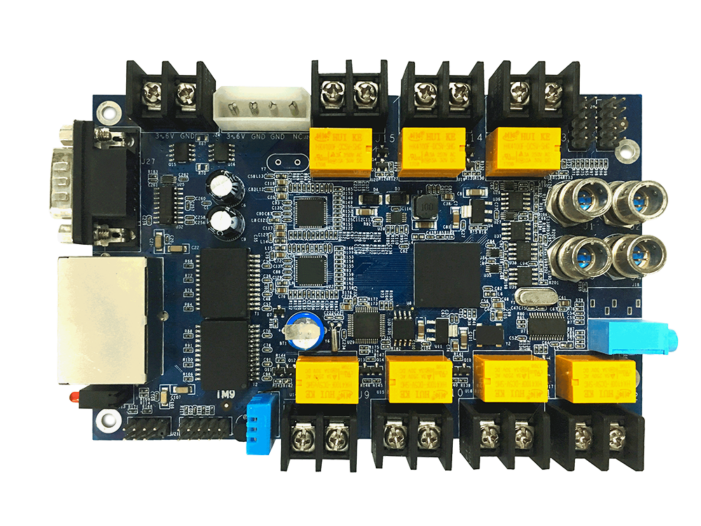
1、Interface descriptions
| S/N | Name | Function | Remarks |
| 1 | Power 1 | Connect DC 3.3-6V power supply for the multi-function card. | Only one is used. |
| 2 | Power 2 | Connect DC 3.3-6V power supply for the multi-function card. | |
| 3 | RS232 | For equipment commissioning | |
| 4 | Ethernet port A | Connected to sending card | The Ethernet port A and B can achieve import/export at random, which can be identified in an intelligent way |
| 5 | Ethernet port B | Connected to receiving card | |
| 6 | Indicator | Indicate power and signal working status | Red lamp for power supply, and green for data signal |
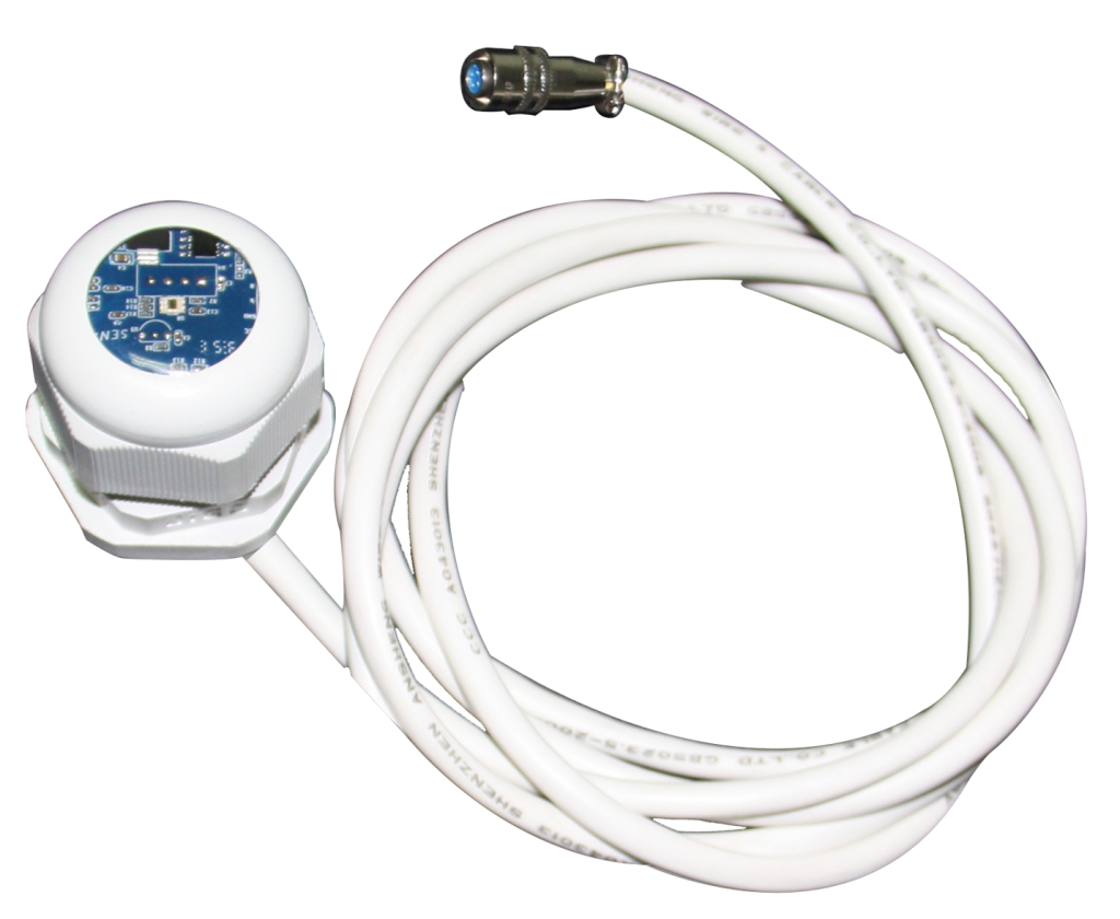
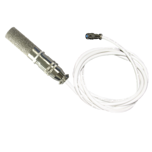
| 7 | Temperature sensor | Monitor the real-time environmental temperature. That can be used to control the switches of air conditioning or radiator fan. | |
| 8 | switches for power control | Used for remote power control, power-on or off delay.
These four switches, J9-J12, can be turned on or off automatically linkage delay, to reduce the impact of the grid. J13-J15 can be individually controlled by different sensor for voltage, humidity, smoke, temperature, and the others needed. |
(Attention the maximum current limit) |
| 9 | Extended monitoring interfaces | Can be used to monitor the voltage, humidity, smoke, and other sensor needed. | Custom-made needed.
If you really need to use them, please consult with our technicians. |
| 10 | Audio | Used to broadcast the audio from the sending card, which can be translated by the internet cable. |
2、Dimension
3、Connection Diagram


