Description

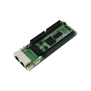
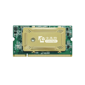
5A-75E Receiving Card Features
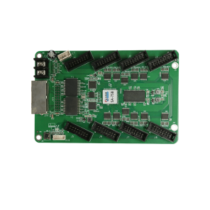
- Integrated HUB75 interface, more convenient with less cost.
- Reduces the plug connectors and malfunction, lower failure rate.
- Superior display quality: high refresh rate, high grayscale, and high brightness with the conventional chips.
- Perfect performance under lower grayscale status.
- Better detail processing: partial dark at row, reddish at low gray, shadow problems can be solved.
- Supports high-precision point-by-point calibration in the brightness and the chromaticity.
- Supports conventional chips, PWM chips and lighting chips.
- Supports any scan mode from static to 64 scans.
- Supports any pumping point and data arbitrary offset to realize various freeform display, spherical display, creative display, etc.
- Supports 32 groups of RGB signal output.
- Large loading capacity.
- Advanced design, high quality components, rigorous aging test, zero malfunction of final products.
- Wide working voltage range with DC 3.3~6V.
- Compatible with all series of Colorlight’s sending devices.
Specifications
| Control System Parameters | |
| Sending device | All series of Colorlight’s sending devices |
| Control area of every card | Full-color: 256×512 pixels |
| Correction area of every card | 256×512 pixels |
| Network port exchange | Supported, arbitrary use |
| Synchronization | Nanosecond synchronization between the card and the card |
| Display Module Compatibility | |
| Chip supports | Supports conventional chips, PWM chips, lighting chips and other mainstream chips |
| Scan type | Supports static sweep to 64 scans |
| Module specifications support | Supports 4096 pixels within any row, any column |
| The direction of the cable | Supports route from left to right, from right to left, from top to bottom, from bottom to top |
| Data groups | 32 RGB data groups |
| Data folded | Supports 2 splits, 4 splits in the same direction |
| Data exchange | 32 groups of data for any exchange |
| Module snapshot | Supports any pumping point |
| Data serial transmission | RGB, R8G8B8, R16G16B16, etc. in the form of serial |
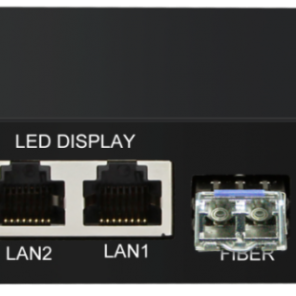
| Compatible Device and Interface Type | |
| Communication distance | UTP cable≤140m
CAT6 cable≤170m Optic fiber: Single-Mode Fiber Converter≤20km Multi-Mode Fiber Converter≤550m (Use RP Repeater to extend unlimited) |
| Compatible with transmission equipment | Gigabit switch, fiber converter, optical switches |
| Power interface | Wire terminal |
| HUB interface type | HUB 75 |
| Physical Parameters | |
| Size | 143×93mm |
| Input voltage | DC 3.3V~6V |
| Rated current | 0.6A |
| Rated power | 3W |
| Storage and transport temperature | -50℃~125℃ |
| Operating temperature | -25℃~75℃ |
| Body static resistance | 2KV |
| Weight | 100g |
| Monitoring Function (in conjunction with multi-function card) | |
| Monitoring functions | Real time monitoring of environment information like temperature, humidity, smoke |
| Remote control | Supports for relay switch to turn on/off the power supply of equipment remotely |
| Other Features | |
| Pixel level calibration | Supported |
| Loop backup | Supported |
| Shaped screen | Supports various freeform display, spherical display, creative display, etc. through the data arbitrary offset |
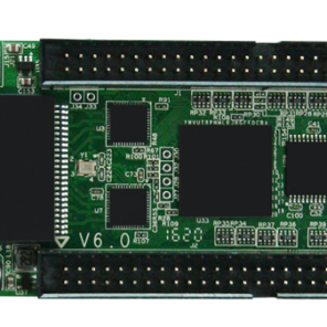
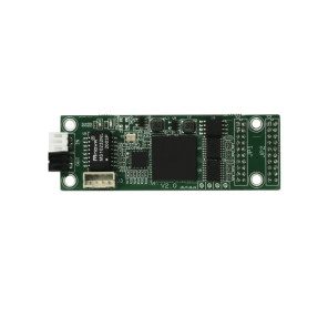
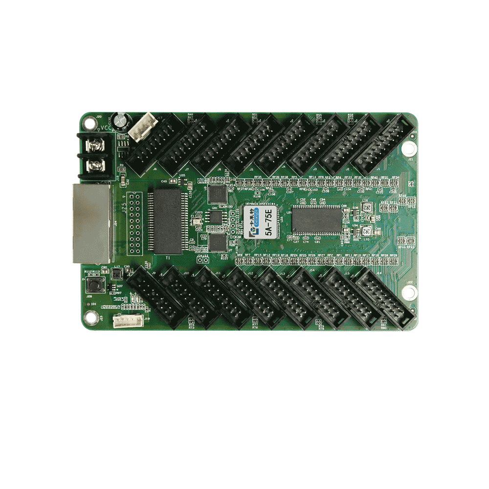
Hardware
| No. | Name | Function | Remarks | |
| 1 | Power 1 | Connect DC 3.3~6V power supply for the receiving card | Only one is used | |
| 2 | Power 2 | Connect DC 3.3~6V power supply for the receiving card | ||
| 3 | Network port A | RJ45, for transmitting data signals | The dual network ports can achieve import/export at random, which can be identified in an intelligent way by the system | |
| 4 | Network port B | RJ45, for transmitting data signals | ||
| 5 | Test button | The attached test procedures can achieve four kinds of monochrome display (red, green, blue and white), as well as horizontal, vertical and other display scan modes | ||
| 6 | Power indicator light | Red indicator light shows that the power supply is normal | D1 | |
| Signal indicator light | Flashes once per second | Receiving card: normal working,
Network cable connection: normal |
D2 | |
| Flashes 10 times per second | Receiving card: working,
Cabinet: Sorting & Highlight |
|||
| Flashes 4 times per second | Receiving card: Backing up senders(Loop Bcakup status) | |||
| 7 | External interfaces | For indicator light and test button | ||
| 8 | HUB pins | HUB75 interface, J1~J16 connected to display modules | ||
2. Definition of HUB75
| Data Signal | Scanning Signal | Control Signal | |||||
| GD1 | GND | GD2 | E | B | D | LAT | GND |
| 2 | 4 | 6 | 8 | 10 | 12 | 14 | 16 |
| 1 | 3 | 5 | 7 | 9 | 11 | 13 | 15 |
| RD1 | BD1 | RD2 | BD2 | A | C | CLK | OE |
| Data Signal | Scanning Signal | Control Signal | |||||
3. Definition of External Interface
4. Dimension